Protip: Practice on cardboard until you’re absolutely certain you have a reproduceable process. 
Unless you take the measured kerf into the calculation, measuring a cut piece will miscalibrate the axes with an error increasing across the platform.
Instead, measure lines center-to-center on a square engraved on a flat surface or the travel of the red-dot pointer on a good steel scale. The doc gives the process, as does a previous discussion:
The result should come out very close to the distance/step calculated from first principles:
mm/step = (belt pitch mm/tooth) × (pulley teeth/rev) / (motor steps/rev)
I set the Ruida controller’s manual step size to 0.2 mm, use its Fast/Slow button to scoot close to the printed target, then make teeny steps to align the dot at the center; it seems easier to do all that on the machIne’s display than long-reaching to the PC’s keyboard.
You must also verify:
- The red-dot pointer is coincident with the CO₂ laser beam at the focus distance
- The laser is focused on the surface of the material
- The material is flat so everything is at the focus distance
For critical items, I fire a test pulse after aligning the red dot to the printed target:
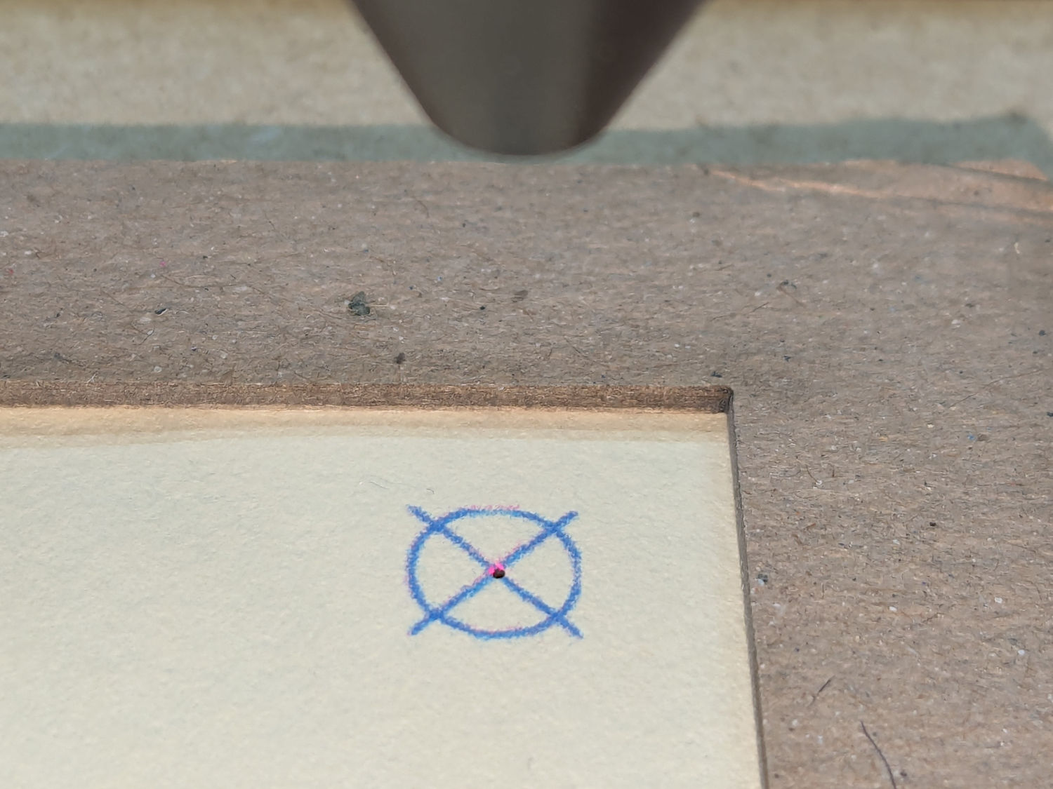
You may get better accuracy with a less-chunky target. I use a vector cross, rather than engraved bars:

That pattern produces the target printed on the paper, although the inkjet-printed lines are much thicker than the vector pattern in LightBurn.
All of which seems is incredibly tedious, but most of it is once-and-done setup. I’ve found I must be grindingly meticulous about everything, because Print-and-Cut has absolutely no sense of humor and will convert “pretty close” accuracy into totally wrong results.