It could also be the gauge dealing with a pwm signal. Whilst the pot will still do it’s thing, an analog gauge won’t necessarily be showing correctly
I’d have to say, I somewhat disagree. The pot is a simple voltage divider, not much to fail.
I’d always trust the analog meter. Both of these show the same on my machine. My digital one on the lps reads the same value as my console analog meter.
They all seem to display the rms value, at least my digital one does. If I pulse it fast enough, I don’t think it’s always had time to completely sampling it..
One way you connect these, the current control actually allows the tube to run at 50% power, some of these work by turning the tube on/off, just like a diode. The drawback is the tube runs the maximum current set by the pot.
Either way the mA meter will show the same rms value.
![]()

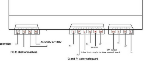
ChatGPT is adamant on this. To create a hybrid set up by connecting the PWM wire to the L on the PSU and GND to G
And to stop the laser firing at start up, find the invert laser / active low setting and flip it.
Google AI says inverting the signal would require complex coding or a hardware fix on the PWM line using a ‘shifter’?
I think if you want help, you need to quit depending on AI. It’s irritating to have to explain what AI didn’t. I know you’re trying to help yourself, but don’t get in a hurry.
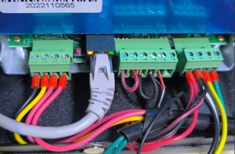
You have it wired to lase anytime the pwm signal is present. The IN of the lps expect either a dc control voltage or a pwm that produces the same voltages.
You have all the interface controls wired for it to turn on. The P is for water protection and the L is laser enable.
You also have a knob that’s plugged into the lps, which isn’t standard, so I don’t know if the schematic with the pot is valid for you.
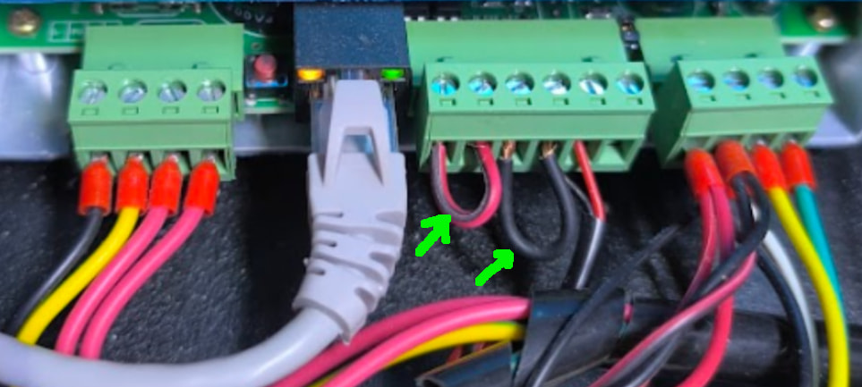
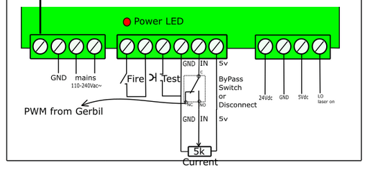
You have both L and P grounded. Do you have a voltmeter? check the pwm voltage when it’s powered up, remove the ground strap from P and L and put switches on them as this photo implies.
![]()
Sorry. Didn’t mean to annoy. I’ll stick with my current set up then, with the pot wired in. If it shows any inconsistencies I’ll add the switches instead as suggested. Cheers for your input. ![]()
![]()
The previous post shows your front panel pot plugged into the supply, at least that’s how it appears. Is that how yours is?
![]()
Yes it is. When it’s set at minimum I get software control of power between 1% and 50% producing 2-3mA to 15mA