Hi there. I decided to transition to Lightburn but to do that I have to change my controller first.
I just got a Ruida kit with controller and I’m trying to replace the old Leetro controller which got toasted. The problem I have for now is that I can’t understand what some of the wiring means when I switch from the Leetro to Ruida because they have different names and don’t know what is what. I know is doable because I saw some members here upgraded this model of laser I have from BRM Lasers but didn’t gave details.
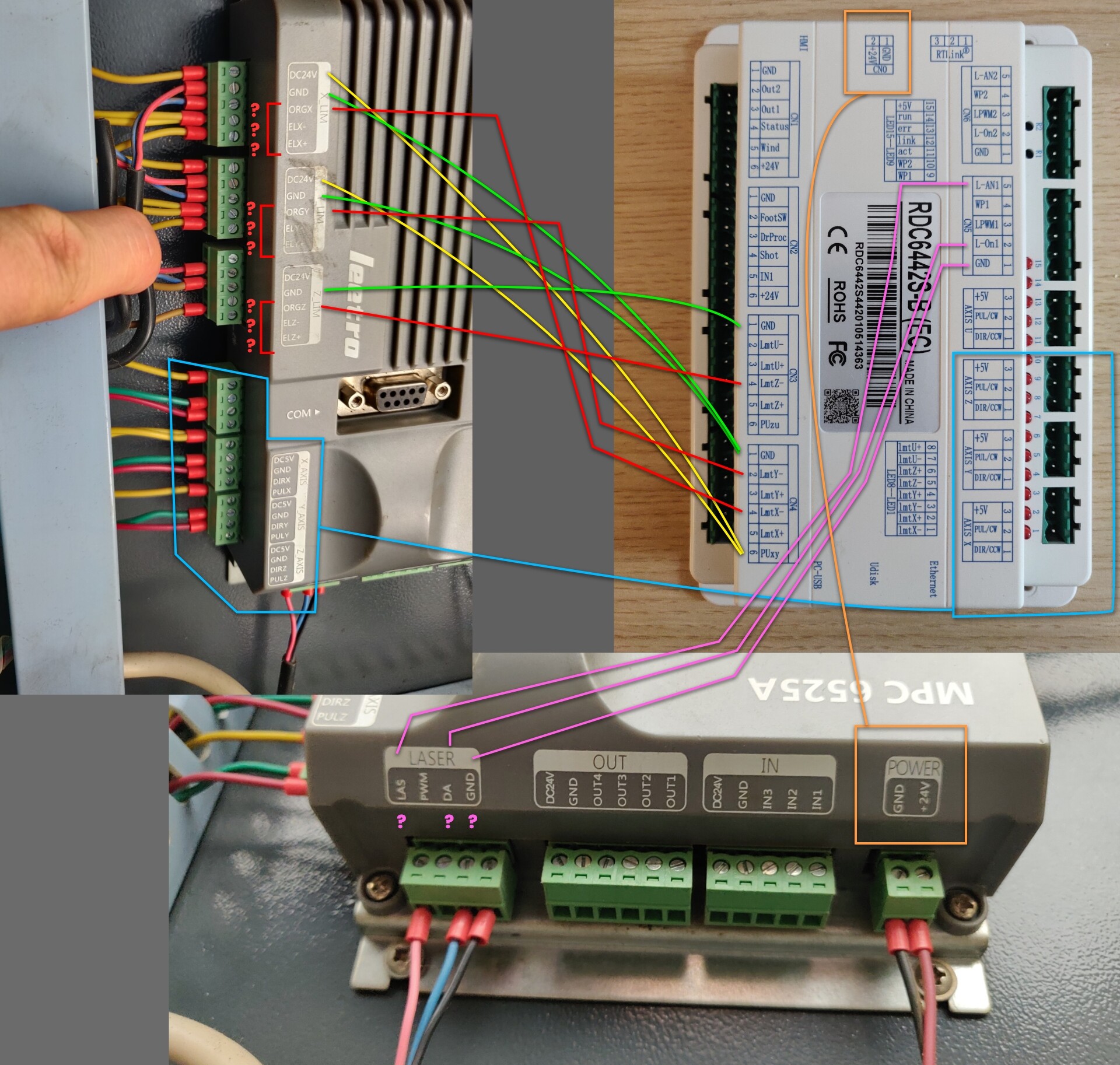
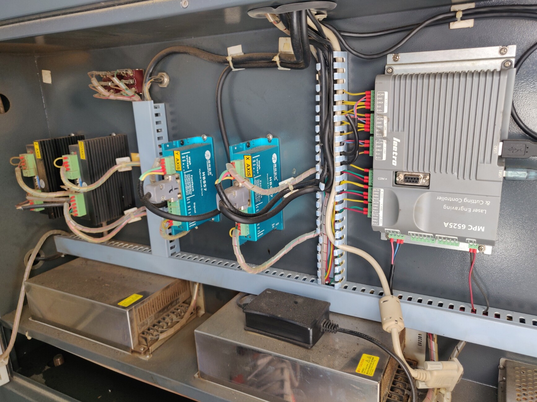
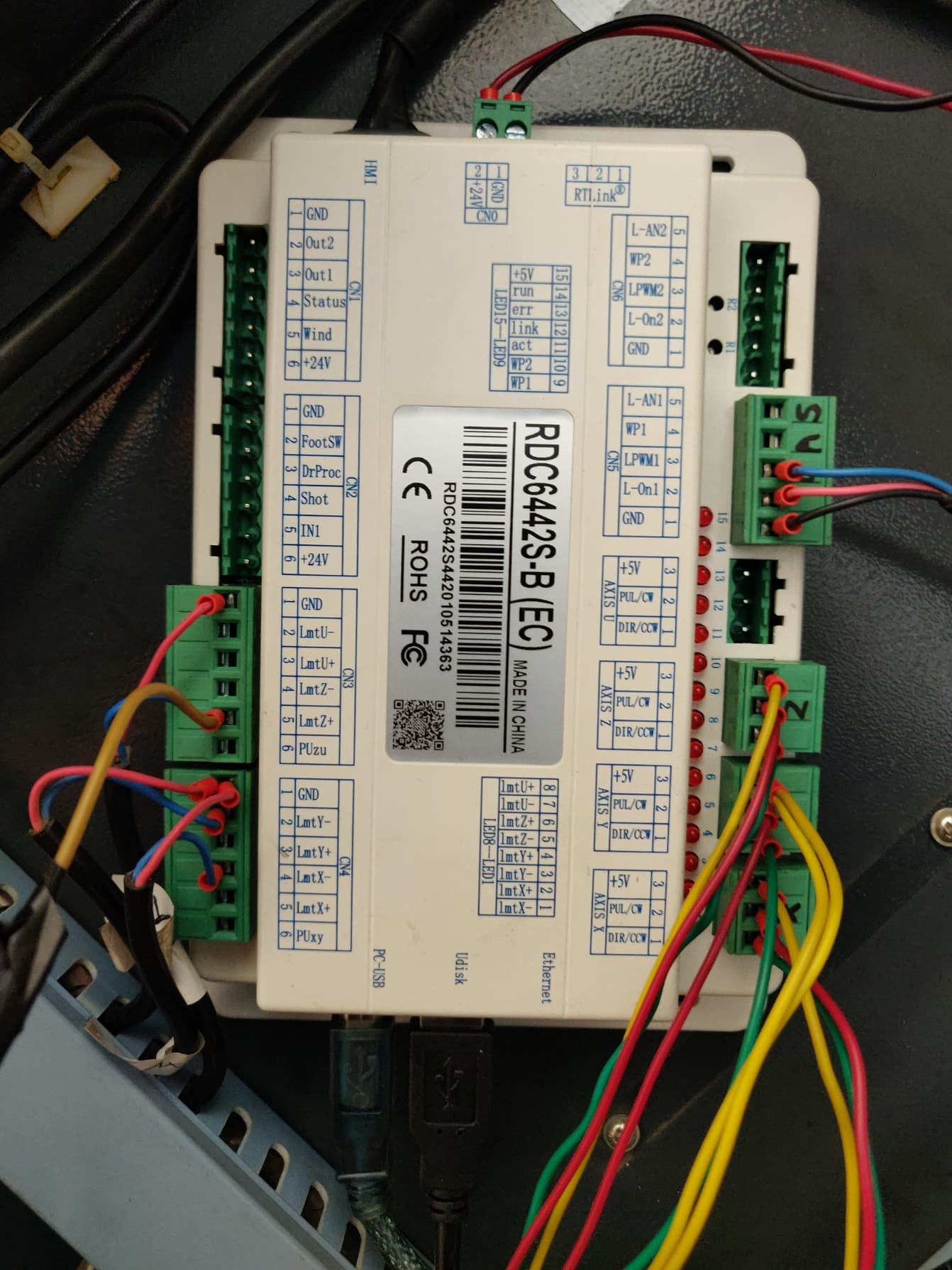
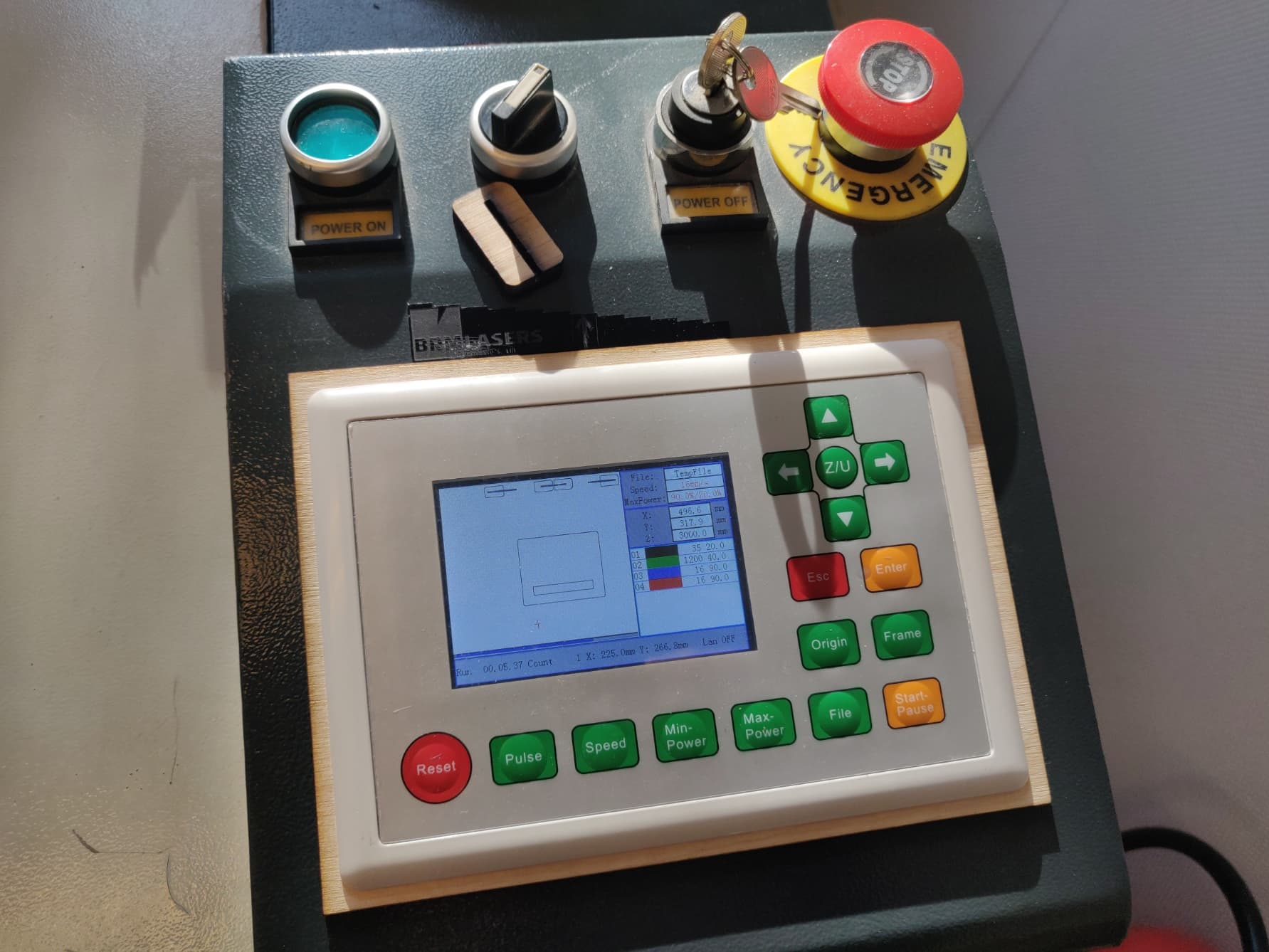
Can anyone please give a hand? Below are side by side both controllers with the Leetro still not disconnected from wires, as it was originally on my BRM laser.
Specially the Red and Pink connections you see in the image attached I need help with. The rest seem clear as they are 1 to 1 named so should be ok in theory.
I can tell you how the Ruida is hooked up. I found a manual for your device. Here is the 6525 manual, in a download link.
The LmtX- or plus has to with which end your limit switches are on, it’s also in the Ruida manual.
So my guess would be that it would go to ELX- and ELY- (External Limits X & Y?) would go to the Ruida LmtX- and LmtY-. All of these manuals lack lots of information when you get down to troubleshooting and it doesn’t help when they call same items by different names.
I think we can help. Do what you can with the manual and compare what you can with the Ruida. At this point that’s the best I can offer.
The only other options is to chase down where each wire goes and that would make it much simpler.
I hope you saved all of your firmware settings in the 6525, they will come in handy
I found the Ruida manual also here and it’s true what you say about the limiters, but now I have another doubt about the ORGX, ORGY and ORGZ, because the Leetro has these extra for the Origin I suppose, but then where do I put them on the Ruida, because it doesn’t have a slot for Origin. Unless I overlap with one of the Limiters and put it at the LmtX- lets say for each of the axes. (see below the red lines)
But then I’ll have 3 wires on a pin then. As currently there are 2 yellow wires at ELX- and a blue at ORGX.
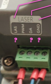
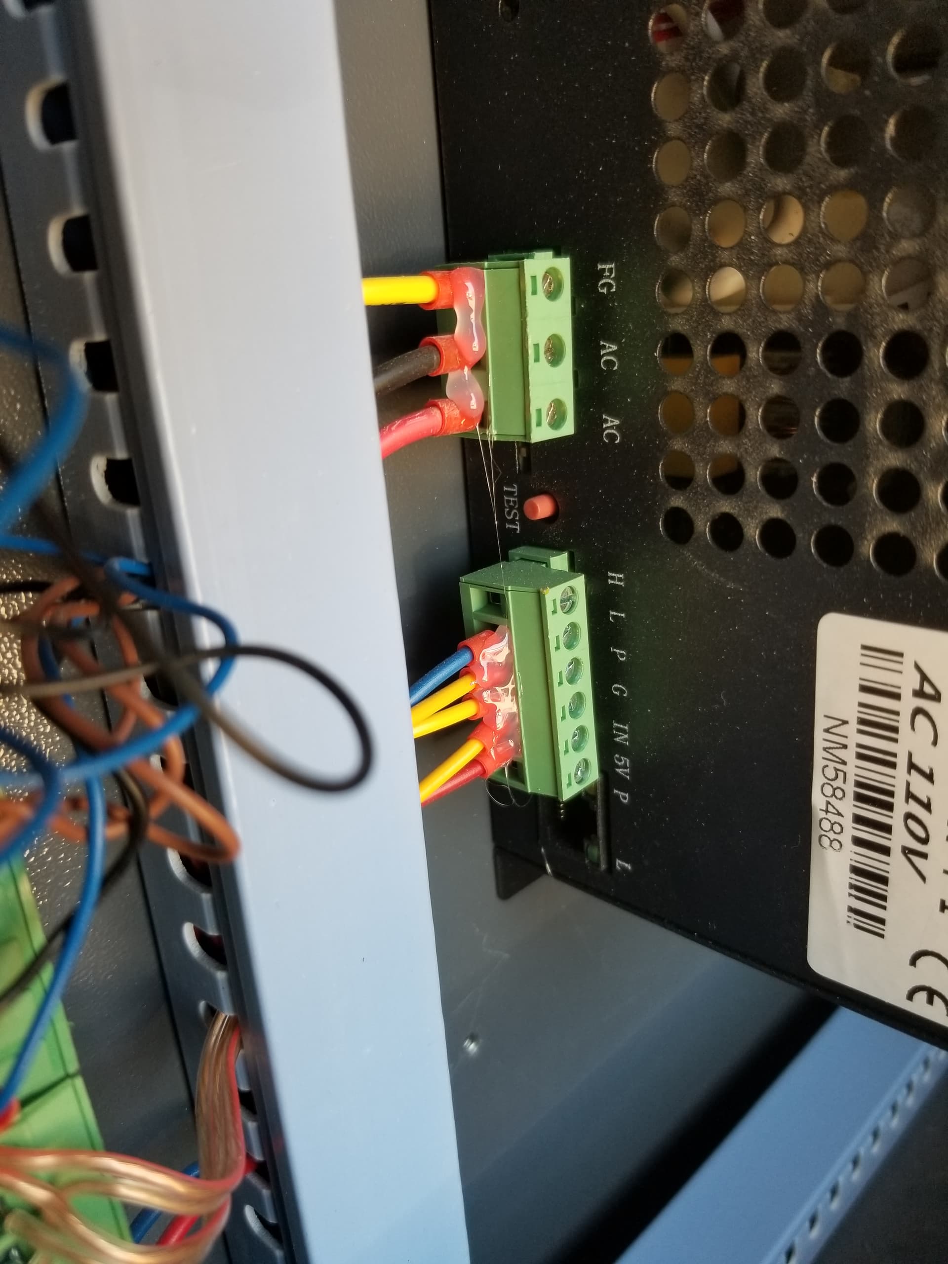
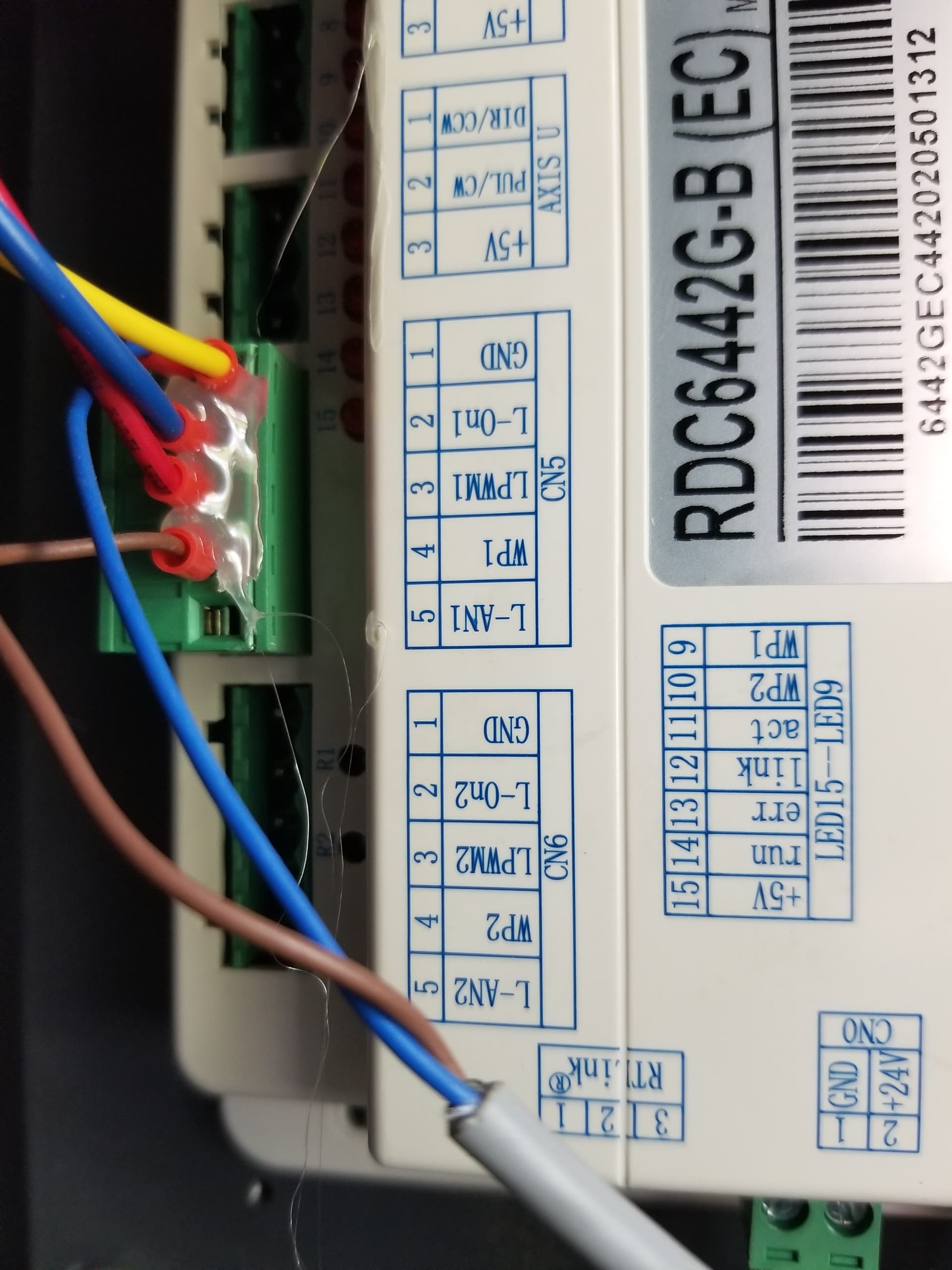
Another thing I noticed is the Laser wire connections. (Pink ones in my drawing)
Seems that the LAS goes to the LPWM1 on the Ruida.
But then what is the DA for? I don’t think is the water pomp. On the Leetro manual is market as Analog Output, whatever that means.
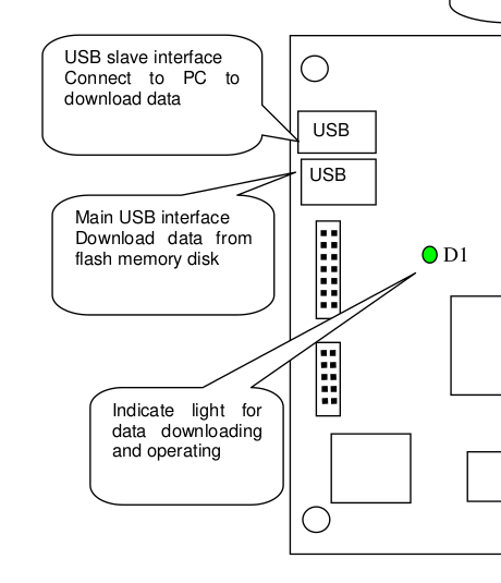
As for the firmware settings, where can I find them to save from the Leetro? And what format is the file? Do I connect somehow via usb to the controller or they are stored in the Laser Cut 5.3 software files on PC?
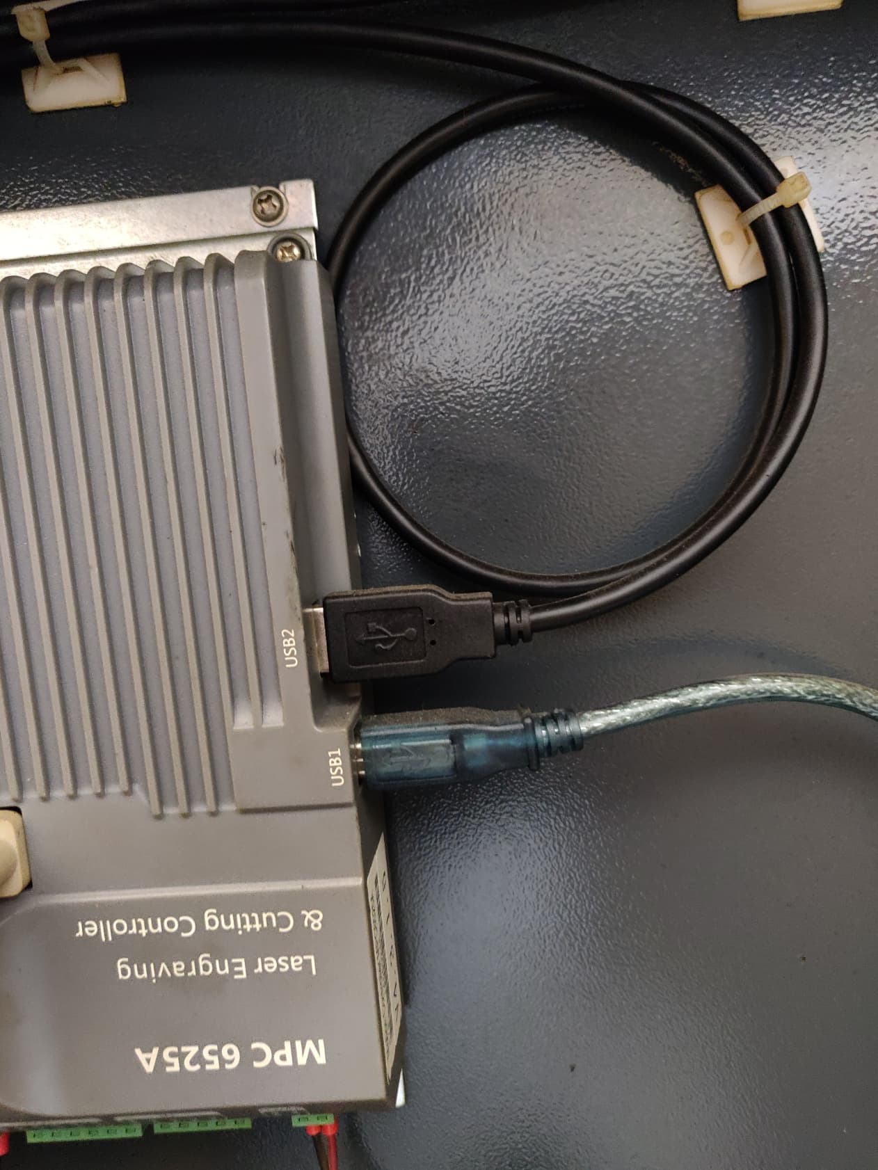
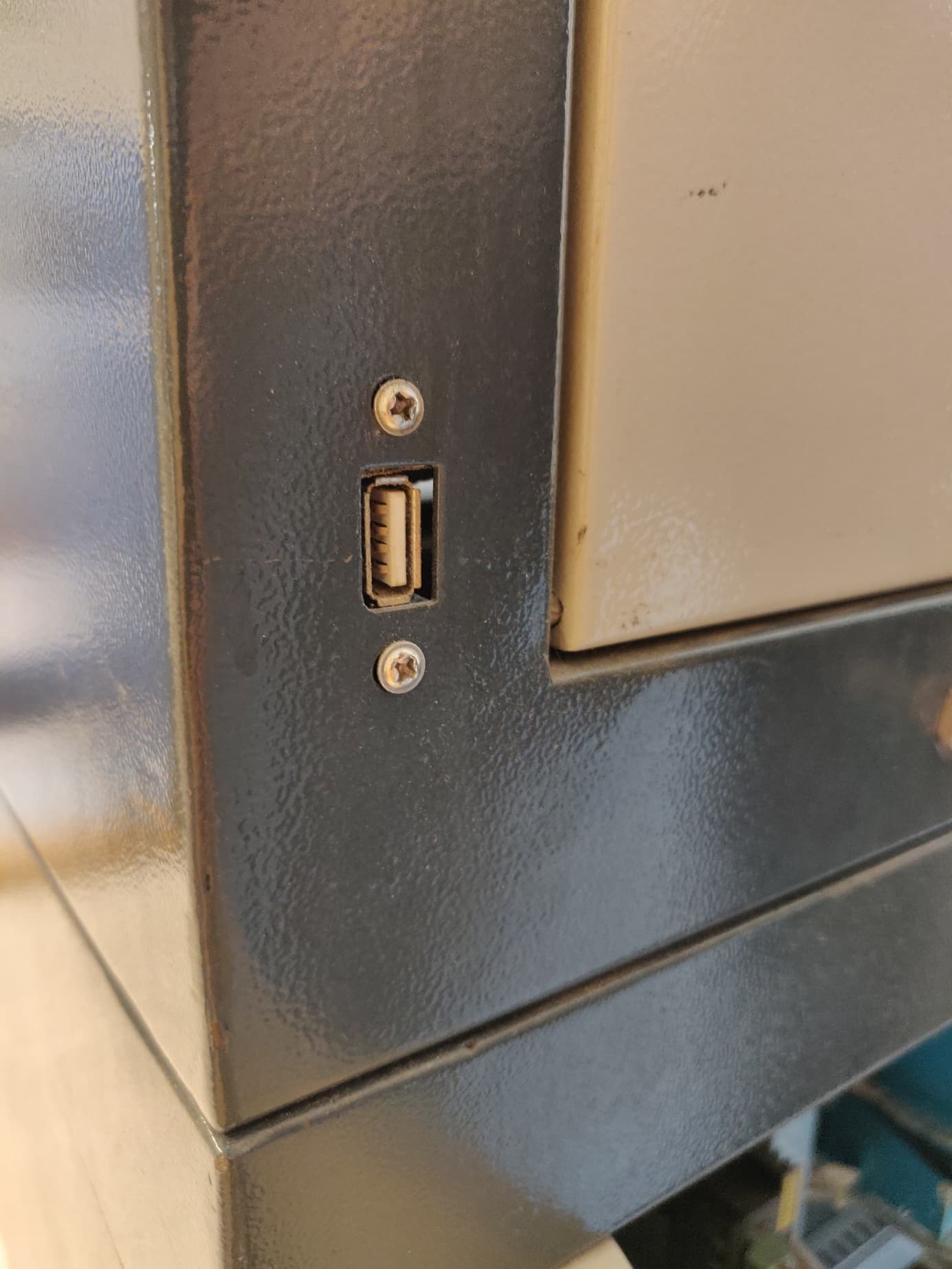
I see I have a second usb that goes on the side of the laser machine. But not sure for what is it, probably to upload files for cutting directly on the machine without PC.
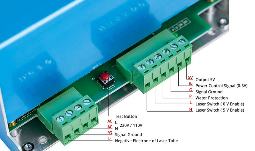
On your controller I have no idea what the DA is for. We know you need to have a ground, a laser enable (LOn1) and the PWM input to the ‘IN’ connection of the psu. The manual really doesn’t show the hardware connections nor does it mention DA that I could find. As per your comment if it’s an analog output it could just go from 0 to 5v for laser control
The more I think of it the more I think the PWM is your control, LAS being laser enable and the DA being a different way to control the psu, analog of the PWM. They may in fact be interchangeable if one is an analog equivalent. You can check that the output of the LAS pin that it goes low when the machine is in run mode, that would enable the psu to fire the laser. That would let the PWM control power level. I’d try and confirm that before I hooked it up via a voltmeter or something.
You will probably have to physically chase down where the ORG* connection go. I have no idea what they are used for.
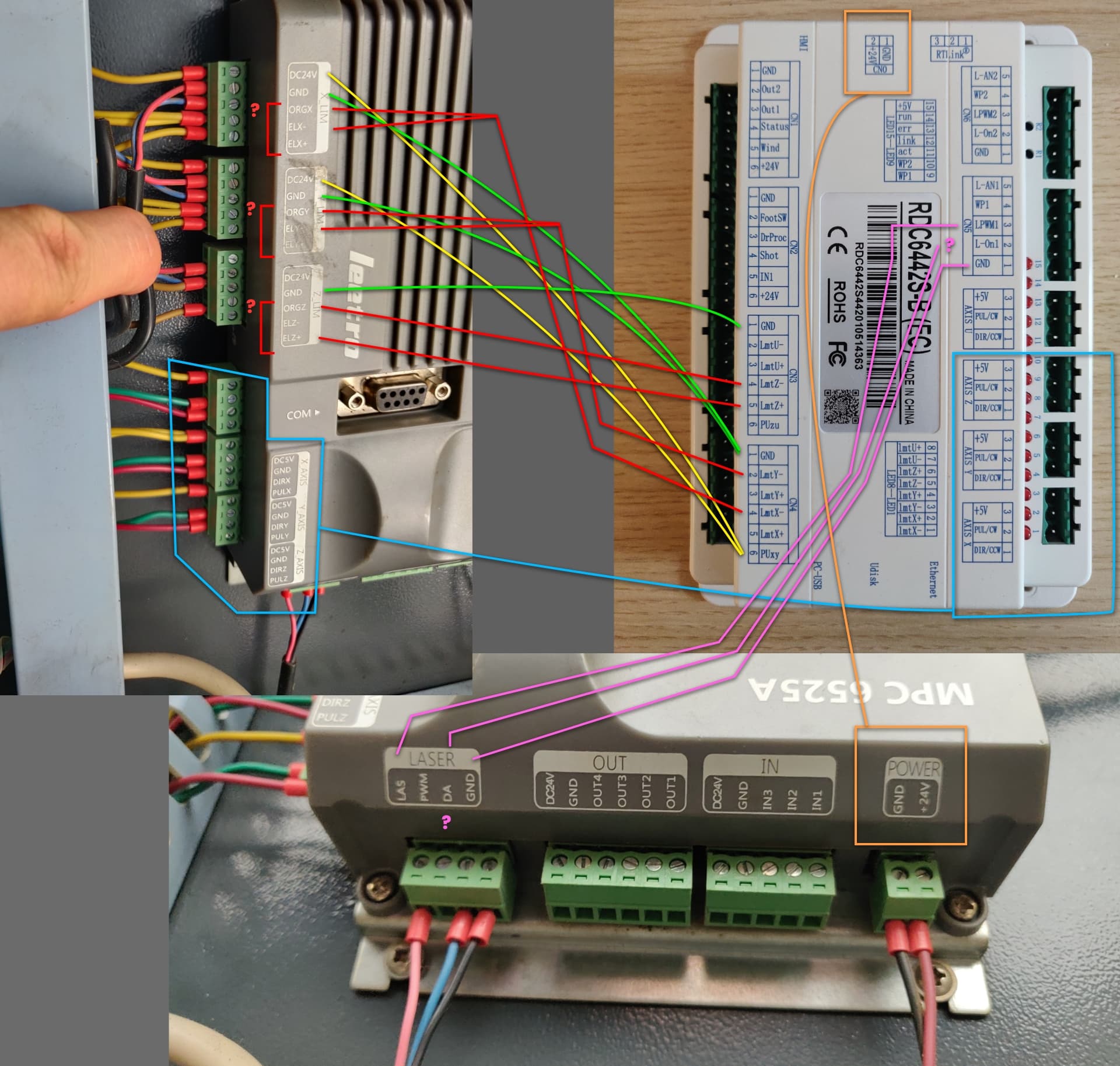
I finally managed to wire the Ruida from the Leetro and run Lightburn. Works really well so far Thank you for the links above. Really helpful.
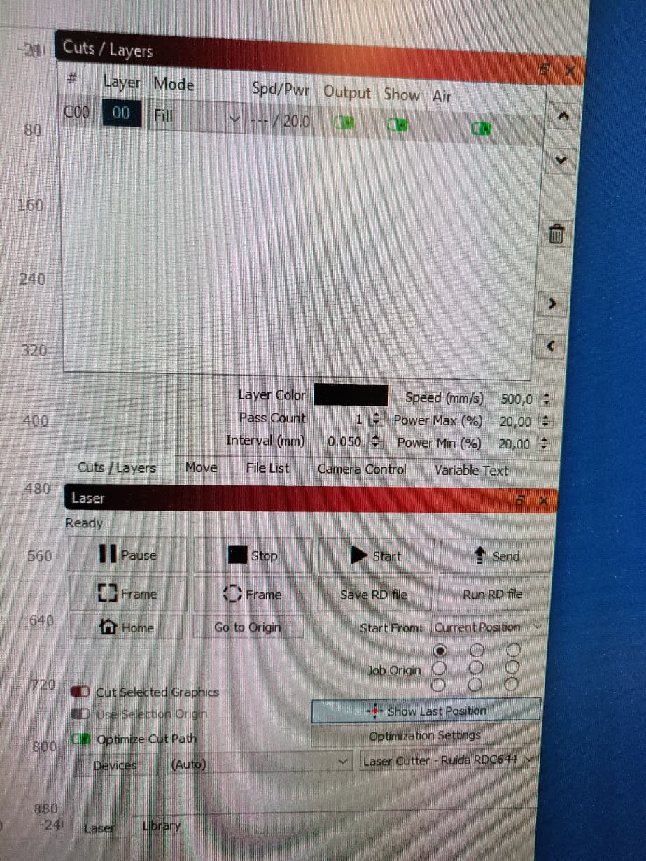
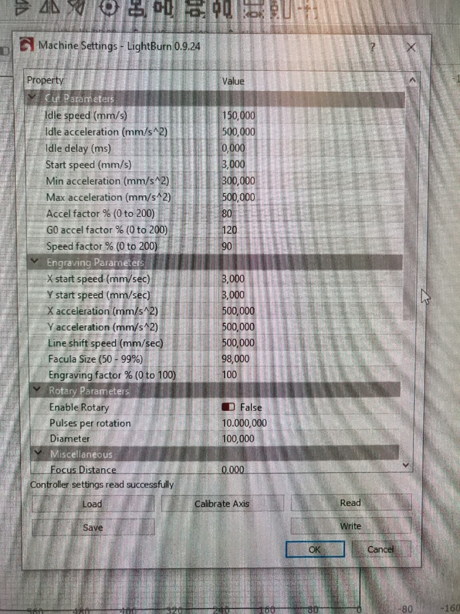
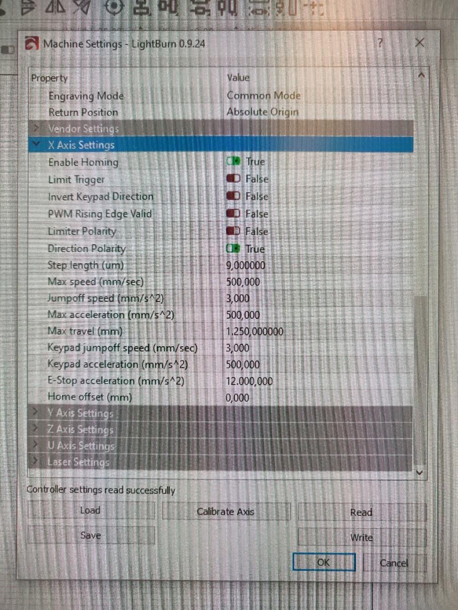
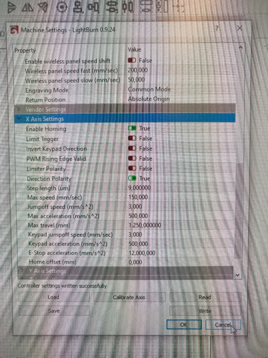
I have some issues though, specially with the speed the laser engraves. Seems to be half the speed i had with the Leetro. Not sure why is it, because I’ve put max speed from Lightburn and nothing changes.
Might be the machine settings, but when i change there the speed, it increases actually the distance of the engraving line, sort of like has more inertia when goes left-right to engrave the lines.
In the controller I have them at 150 speed, but when i shift to 500 I get this lag or inertia left-right.
Any idea how to fix?
Another issue, that is a bit strange, is how the origin of the job works.
On the Leetro for example whenever I had the head of the laser the laser was positioning the drawing relative to head position. So was easy to just put sheet material, move the laser head to one corner and start.
Now it works only via software like that if i push Start. If I do it from the Ruida keypad starts somehow relative to where the drawing is on the table. Maybe I have to set the origin on the Keypad to work somehow because when I hit origin, doesn’t come back to the origin of the laser Machine like the Leetro was doing. Bit annoying. But it works when i press Home from Lightburn.
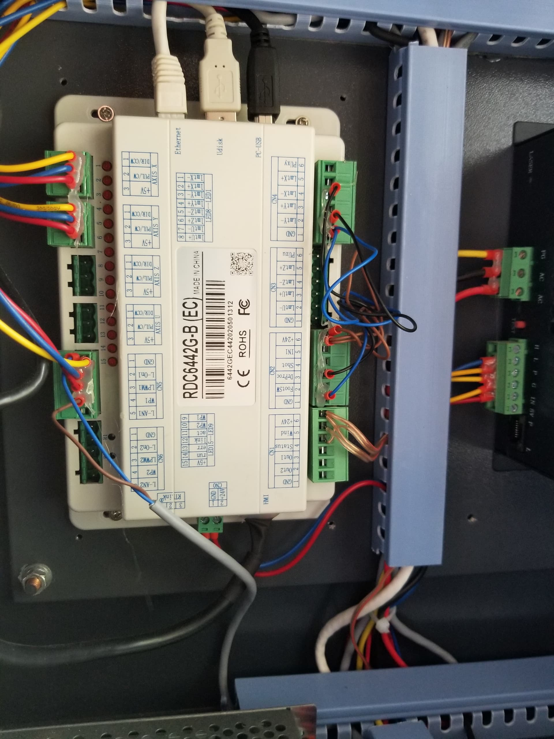
For the ones that need to make the wiring from Leetro to Ruida here are the pics with the final connections. I still didn’t have time to fix the Z axis limiter but I can live without for now. The blog above has some info on that anyway.
As for the software while it works I didn’t manage to solve the issue of the slow engraving. I think there’s some settings somewhere that limits it or gives more swing and travel time to the head when engraving the lines left-right. I tried it with the included RDWorks that came with the Ruida and with that one seems fine, so it’s definitely something in Lightburn. I also installed the last version so shouldn’t be any bugs I suppose. It’s a shame because the software is really the best but if I can’t solve this issue, it just takes ages to engrave.