I’m currently building a CO2 laser machine for my small business and I’m using the MKS DLC32 v2.1 board, a MYJG-60W CO2 laser power supply (LPSU), and TB6600 stepper drivers for my NEMA 23 motors.
However, I’m still very new to electronics and I’m struggling to figure out the correct way to wire everything safely and properly.
Specifically, I have a few questions:
How should I connect the MKS DLC32 v2.1 to the MYJG-60W LPSU?
– Which pins go where?
– Do I need any resistors or additional components?
Can someone help me draw or show a clear wiring diagram for this setup (MKS DLC32 + LPSU)?
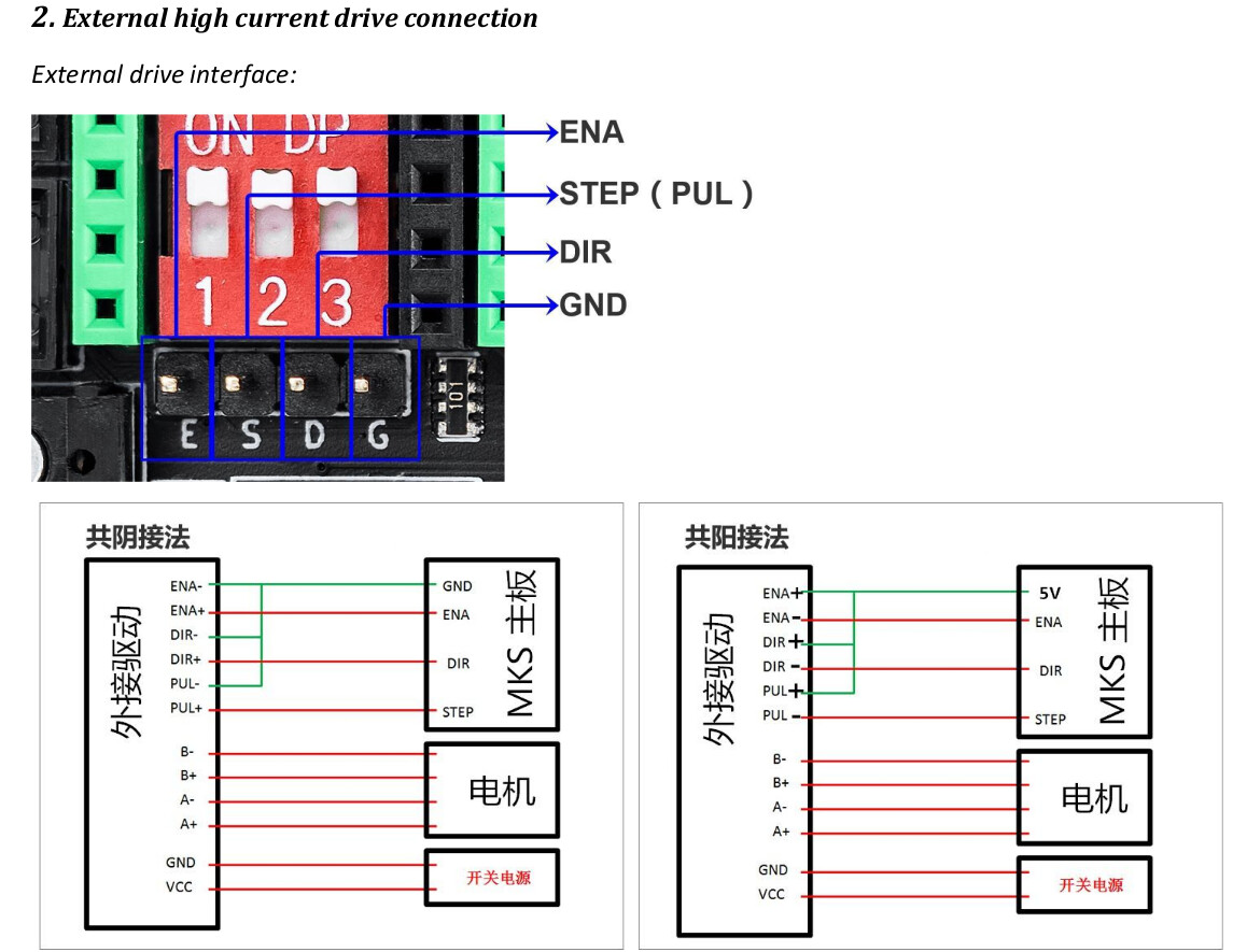
How do I connect the TB6600 stepper drivers to the MKS DLC32?
– Which pins control DIR/STEP/ENA?
– Do I need to set anything specific in LightBurn or firmware?
My goal is to make this machine work reliably and safely. Any help or guidance – even simple sketches – would be greatly appreciated!
If you haven’t done something like this before, there is a lot to learn and I’m tempted to recommend using FluidNC for this DIY project. It’s a robust and versatile firmware which runs great on the DLC32.
Specifically the external TB6600 stepper drivers might require some tweaking of the step pulses, which could be difficult with the MakerBase firmware
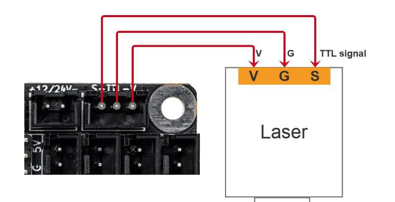
I used this connector for pwm. It’s a ttl voltage, but that ID is above the ground connection. I used only S (pwm) and G (ground) from this connector to the lps.
There are two ways to connect these to the lps. The laser power supply (lps) has an IN voltage control and a laser enable pin, usually L for a low enable or H for a high enable. The IN voltage (pwm or analog) controls the lps current limit.
You can wire the PWM to the IN pin, wiring the L pin via a switch to ground to enable the laser. This is usually available to the operator. The advantage of this approach is that the software is actually controlling the tube as the analog device it is. The drawback is you have to get your control board to generate a pwm signal if you want to pulse the device.
Many of the K40 and grbl control boards wire a pot that is simply a voltage divider to apply a DC 0 to 5V to the IN pin. They PWM would go to the H pin of the lps. The drawback with this method is that the tube is turned on/off like it’s a digital device, lasing at whatever the IN current limit is set.
In either event, I’m not sure how you’d pulse the machine for alignment purposes or tests.
You get to pick which you want
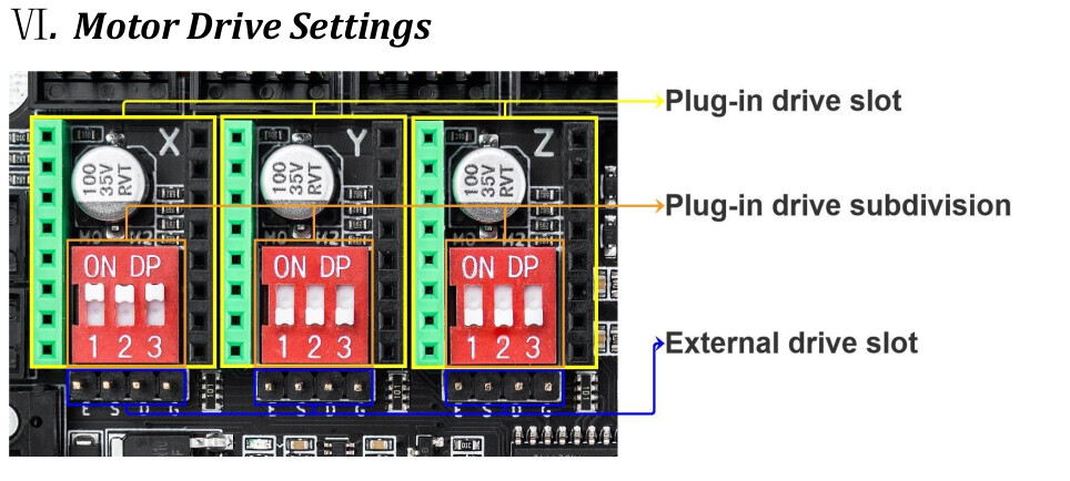
Can’t do too much about you motor stepper driver. When I did this I connected my DLC32 directly to the my stepper motor driver using the external driver slot. Ensure you know the current limits that the board can supply.