I’m looking for suggestions on how to go about connecting my 2.5W laser diode to an Arduino running GRBL 1.1h with a CNC Shield V3. My main objective is to be able to get the laser on PWM and better grayscale.
I’ve had this laser for a couple years and ran it off my CNC router’s breakout board through a solid state relay via mach3. But now I have it setup on a new machine with Arduino UNO (GRBL 1.1h) , CNC Shield V3 and using the same solid state relay attached to the Z+ and Ground pins to enable the laser. This setup is working however I’d like better grayscale and to be able to adjust laser power through software.
Any suggestions on a driver board or schematic would be greatly appreciated.
Here’s more information I’ve gathered if anyone has any ideas.
The output from the Arduino, V3 shield is running 1kHz. The output of the power supply is 12V and the current is 1.125A when enabled. My understanding is the UNO is 8 bit so only need to set 256 power levels so I’ve set $30=255 and I’ve set S-value max to 255 in Lightburn. Below is the output from the Z+ pin at different power settings through that range.
The laser module has precious little doc, but the last item stands out: “imported laser diode + constant current driver board”. The Amazon listing doesn’t include a connector pinout, but I’d expect at least three active pins: +12 V supply, ground, and PWM.
That suggests the diode runs at a constant current and you can vary the intensity with a digital PWM signal by directly feeding it the Arduino’s output. The internal “constant current” driver will then handle the conversion to whatever the diode needs to stay happy.
So, if you can figure out the laser module’s input pins, you (probably) don’t need an interface board at all!
Thanks for your input ednisley. I wish it were that easy to find a 3rd input to the laser. Unfortunately the only pcb board on the laser sits under the fan and appears to only have + / - pads for the fan and laser diode which appear to be connected. The power brick appears to just be a standard 12V brick with AC in and DC out with 2 wires nothing more, however I have not tried opening the case to see if there’s any additional control pins internally as I suspect not and don’t want to ruin the enclosure.
Then you (almost certainly) have what’s intended to be a constant-power laser, because its internal regulator will do its best to maintain the same current through the diode regardless of the external conditions.
However, another bullet item says “Working Current: 170mA/900mA”, which suggests there’s some way to vary the current. If it’s not PWM and doesn’t have a separate control line, they’re being really coy about how it’s done.
Some experience with Amazon listings tells me that not everything need be true at the same time and might not even apply to the pictured item.
Given a lack of doc, all that is best-guess supposition.
I believe you are correct. The link to the laser I posted is “similar” to the one I have however like I said I’ve had it for a few years and didn’t remember where I purchased it from. I’ve just found where I purchased it from on banggood. I purchased it in 2018 and it was called “EleksMaker® LA03-2500 445nm 2500mW Blue Laser Module” The link to the item on bangood is no longer valid but when I search for that model I found this EleksMaker LA03-2500 Blue Laser Module With Heat Sink 445nm 2500mW Aircraft Aluminum for CNC DIY Laser Engraver Machine Parts - BeamQus that lists the specs as 2500mW constant laser power.
My original thought was to connect the power brick to a board like the one I previously posted, adjust the output voltage to 12V and the output current to 1.125A then connect the Arduino Z+ & Gnd to the TTL in to the board then connect the laser to the laser + / - output. Cross my fingers and hope it works lol.
I have some electronic knowledge but most has been forgotten. Do you see any problem with the direction I’m going or do you have any alternatives I should be looking at? Or should I just purchase another laser module with PWM control built in?
By definition, the laser’s internal constant-current control will attempt to maintain a constant current through the laser diode, regardless of the input voltage variation. Changing the input voltage will have no effect on the laser power, until the voltage falls below the level the regulator can handle, at which point the whole thing shuts down.
Remember: power = voltage × current
Under normal circumstances (when it’s connected to an ordinary power supply), the internal regulator will draw more current from the supply as the input voltage drops, because that’s how it can deliver constant power to the diode. Likewise, if the supply voltage rises, it will draw less current, again supplying constant power.
So trying to reduce the laser’s power by strangling its current. The internal regulator will attempt to draw whatever current it needs to maintain constant power into the diode (because that’s Job One), but the supply won’t allow that, whereupon the input voltage collapses and the whole thing stops working.
Varying the scanning speed is the only way to control the energy delivered to the workpiece: more speed at constant power = less energy per millimeter traveled. Unfortunately, CNC machines tend to have low top speeds compared to laser machines, so the high end isn’t usefully high.
If you need variable laser power, that’s what the laser module should deliver.
Thanks for the information you’ve provided. I understand what your saying but I’m really just not certain the laser diode has any type of current or power control built onto it’s pcb as it’s basically a flat disc with a few pads as I recall. Makes me think it’s more likely the ps itself may have the constant current built in. Either way I’ll probably take your advice and get a new laser diode after the holidays, that would certainly be the easiest route to take. And since I believe someone has purchased the TTL modulated board off my Amazon X-mas list I’ll probably tinker with that as well. Thanks again for your help.
Hi,
looking through the docs for arduino cnc shield v3
v3.00 supports 4 axis
v3.10+ has support for variable spindle
you can check with a meter if there is a connection between arduino pin11 and limit z-axis or pin11 and variable spindle PWM.
Default grbl 1.1h supports pin11 PWM without reconfiguring and recompiling, but I suggest going through config.h and setting up what you need and compiling.
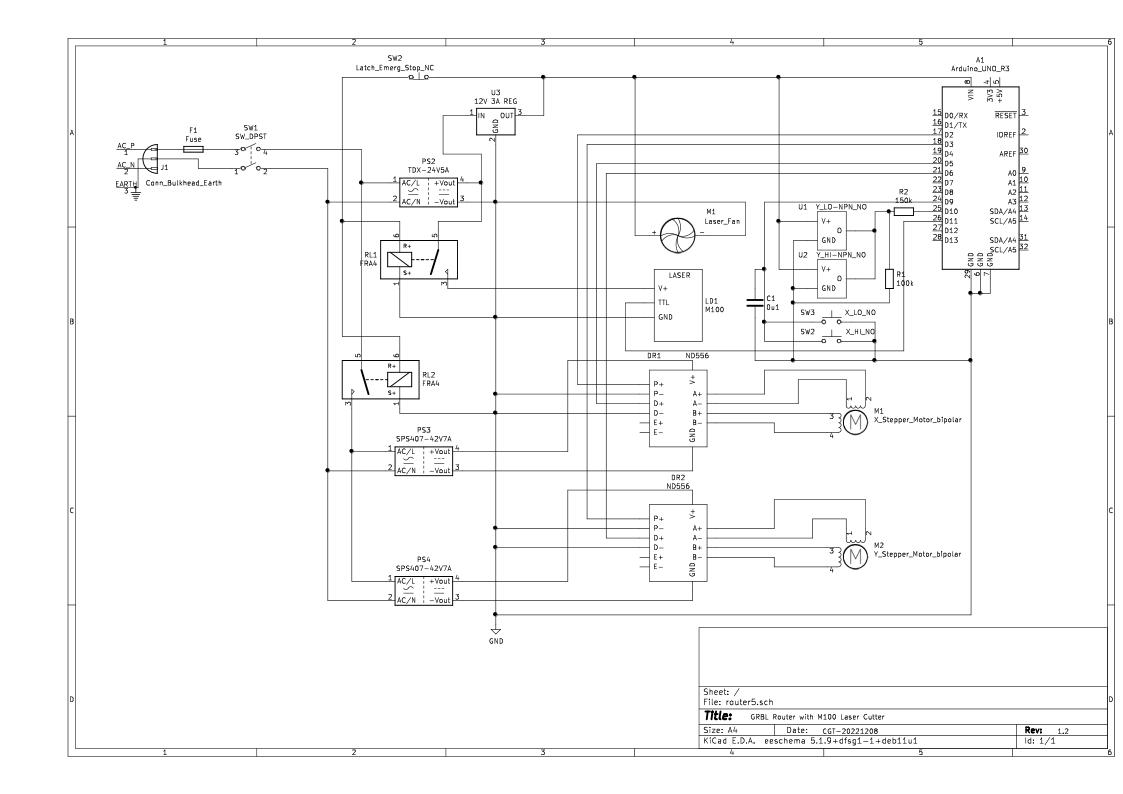
I made my own interface board. The pin11 goes direct to my Atomstack M100 diode laser TTL level pwm input.
Get your star earthing correct between the laser power supply and arduino.
I have good PWM control from the V3 board as indicated in one of my previous posts. The problem I have is interfacing that 0-5V PWM to the laser power control side. Mind sharing your schematic of your interface board?
Thanks, but that circuit won’t help me out as the magic on your machine is happening in the laser diode circuitry of the box labeled LD1 M100. My laser doesn’t have 3 input pins only DC+/-. That’s how I can get it to work with a SSR but that’s on / off only. I have a new laser diode ordered should receive it in a few weeks that has the 3 inputs.
Just had a look at your laser module. Did you order an Atomstack ?
If you want to experiment with your current laser module try a solid state relay between the power supply and laser, switched by the PWM output, maybe TLP3543.
I ordered a laser diode from alliexpress that I seen reviewed on youtube. A SSR is how I’ve been using it but my objective is to be able to get true grayscale not just dither.