markcfg7 is a 174mm lens nd markcfg0 is a 112 lens. When Iload the markcfg0 LB won’t engrave.
The markcfg7 file is for the lens shipped with the laser. I have no idea what the other markcfg files are used for. Never heard them associated with a specific lens.
The only ones I’ve seen when shipped with multiple lenses are copies of the EZCad directories, each having all of these markcfg files, but the only one used is the markcfg7.
My markcfg7 file is for my F420mm and the other lenses have been corrected by a cor file for each that I created.
Did your machine come with multiple lenses?
![]()
Yes, this is the file for the 112mm lens
Laser Type: Fiber
Fiber Source Type: IPG_YLP
Field Size: 112 mm
Field Angle: 0 °
Enable PWM: Yes
Min Freq: 1 kHz
Max Freq: 20 kHz
Enable Q-Pulse Width: No
Open MO Delay: 8000 ms
Galvo 1 is X: No
Galvo 1 Negate: No
Galvo 1 Scale: 0.89686 %
Galvo 1 Bulge: 0.99
Galvo 1 Skew: 1
Galvo 1 Trapezoid: 1
Galvo 2 Negate: No
Galvo 2 Scale: 0.97276 %
Galvo 2 Bulge: 1.07
Galvo 2 Skew: 1
Galvo 2 Trapezoid: 1
Frame Speed: 3000 mm/s
Red Dot Always On: No
Red Dot Offset X: 0 mm
Red Dot Offset Y: 0 mm
Red Dot Scale X: 1.01
Red Dot Scale Y: 1.013
Red Dot Rest Pos X: 0 mm
Red Dot Rest Pos Y: 0 mm
Start Marking Port: None
Start Mark High/Low: High
Ready Light Port: None
Ready Light High/Low: High
Door Protect High/Low: High
Done Mark Port: None
Done Mark Input High/Low: High
Red Light Port: None
Red Dot High/Low: High
Door Protect Switch Input: None
End Delay uS: 150 uS
Jump Speed: 1000 mm/sec
Laser Off Delay uS: 150 uS
Laser On Delay uS: -50 uS
Max Jump Delay uS: 500 uS
Max Jump Distance: 10 mm
Min Jump Delay uS: 500 uS
Polygon Delay uS: 50 uS
Laser Busy Port: None
SPI Simmer Current: 80 %
Laser Busy Light High/Low: High
this is the file for the 174mm lens
EZCad Config Summary:
Click Next if settings are correct.
Otherwise import another config or cancel.
Laser Type: Fiber
Fiber Source Type: IPG_YLPM
Field Size: 174 mm
Field Angle: 0 °
Enable PWM: Yes
Min Freq: 1.6 kHz
Max Freq: 1000 kHz
Enable Q-Pulse Width: Yes
Open MO Delay: 8000 ms
Galvo 1 is X: No
Galvo 1 Negate: No
Galvo 1 Scale: 0.83542 %
Galvo 1 Bulge: 0.96
Galvo 1 Skew: 1
Galvo 1 Trapezoid: 1
Galvo 2 Negate: No
Galvo 2 Scale: 0.89767 %
Galvo 2 Bulge: 1.04
Galvo 2 Skew: 1
Galvo 2 Trapezoid: 1
Frame Speed: 3000 mm/s
Red Dot Always On: No
Red Dot Offset X: 0 mm
Red Dot Offset Y: 0 mm
Red Dot Scale X: 1.014
Red Dot Scale Y: 1.018
Red Dot Rest Pos X: 0 mm
Red Dot Rest Pos Y: 0 mm
Start Marking Port: 15
Start Mark High/Low: High
Ready Light Port: None
Ready Light High/Low: High
Door Protect High/Low: High
Done Mark Port: None
Done Mark Input High/Low: High
Red Light Port: 4
Red Dot High/Low: High
Door Protect Switch Input: None
End Delay uS: 150 uS
Jump Speed: 1000 mm/sec
Laser Off Delay uS: 150 uS
Laser On Delay uS: -50 uS
Max Jump Delay uS: 500 uS
Max Jump Distance: 10 mm
Min Jump Delay uS: 500 uS
Polygon Delay uS: 50 uS
Laser Busy Port: 5
SPI Simmer Current: 80 %
Laser Busy Light High/Low: High
When I use these the laser won’t burn
Thanks
What kind of fiber laser do you have? Make/Model?
Do you have a JPT MOPA laser source?
Are there any markings on the lens housing to identify each of your lens? Perhaps something similar to this “SL-1064-174-254G”?
Otherwise, what is the distance (when focussed) from the bottom of the lens flange to the work surface? (see: How to Focus a Galvo Laser)
To setup your other lens, I would advise you to ignore your markcfg0 file, and duplicate the laser settings that are working. Use the duplicated device to setup the other lens as shown in this video.
Second lens has IPG-YLPM, first one IPG-YLP.
Second has QPulse enabled. Betting that’s the markcfg7.
My understanding is the markcfg7 file is a factory file for exporting settings, markcfg0 is just a bunch of place holders. Its been a while but from memory running ezcad’s corefile2 utility doesn’t even produce a markcfg file, and ezcad doesn’t use a markcfg file, it uses a .cor file.
PLEASE anyone if this is not correct let me know, been a couple years since I messed with all this.
All settings between the lenses should be the same,
Except scale/bulge/skew/trap.
Suggest using which ever lens works, import that markcfg7 file, then run 9 point correction. Set up second lens, use same settings, and run 9 point correction for that.
With ezcad each lens there should be a separate installation of ezcad, and each installation should have its own lens correction file, and if it came factory installed, a markcfg7 file.
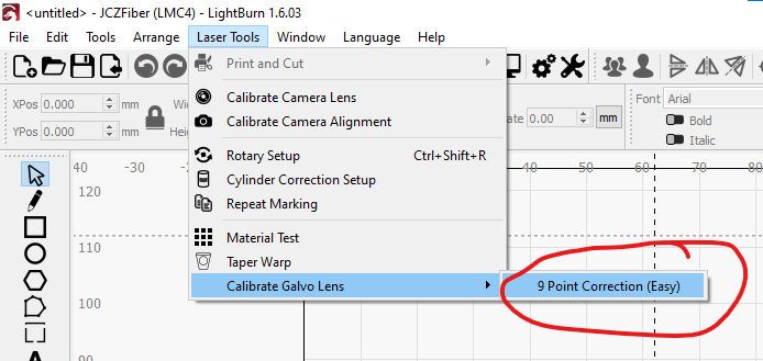
Where do I find 9 point correction
Look here in the ‘Laser Tools’ menu;
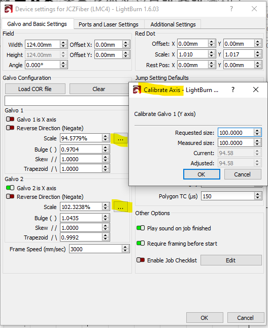
After you have done the 9 Point Correction, it’s a good idea re-check the scale of the output (of a 100mm square for example) and make any final small adjustments using the ‘Calibrate Axis’ form (if needed);
This topic was automatically closed 30 days after the last reply. New replies are no longer allowed.

