Help with my new laser module LU2-10A on Ortur Master 2

Hi ! I installed the laser module LU2-10A on my Ortur Master 2 and when I try to homing my laser, it doesn’t work. It’s like it doesn’t sense the home button but it really does touch it. When the problem occur, Lightburn write me this. (In french)

OLF 142.

Grbl 1.1h [‘$’ for help]

[MSG:Check Limits]

[MSG:‘$H’|‘$X’ to unlock]

ALARM:9

Défaillance de l’autoguidage. Impossible de trouver l’interrupteur de fin de course à distance de recherche. Défini comme 1,5* max_travel lors de la recherche et 5* lors des phases de localisation.

What do I need to do to fix the problem ? :face_exhaling:

I would hazard a guess that the laser is physically larger and preventing the homing switch from being triggered.

ALARM 9 is caused by the switch not being reached and triggered when homing is requested.

Loose belt drive pulleys can also cause this if the engrave head seems to move too little.

A chassis that is stuck, bent or binding can prevent the engrave head from arriving home.

Homing in the wrong direction can cause an engraver to not arrive home.

It can also occur if homing is requested on a machine without the required switches.

Please confirm that the limit switches are present, and that the engraver seems to travel far enough toward them to activate them.

After this, we can proceed with the next steps.

1 Like

Ok so I’ve check everything you mentioned and unfortunatly it didn’t work. I probably did something wrong when I’ve set up my new module laser but don’t know what. :confused:

Here’s some photos to check out my installation and maybe you’ll see something.

Thank you in advance for your help !


1 Like

Ahh… I think I see it.

It would be wise to shut off the power to the engraver, and unplug the USB cable before making this adjustment to your equipment.


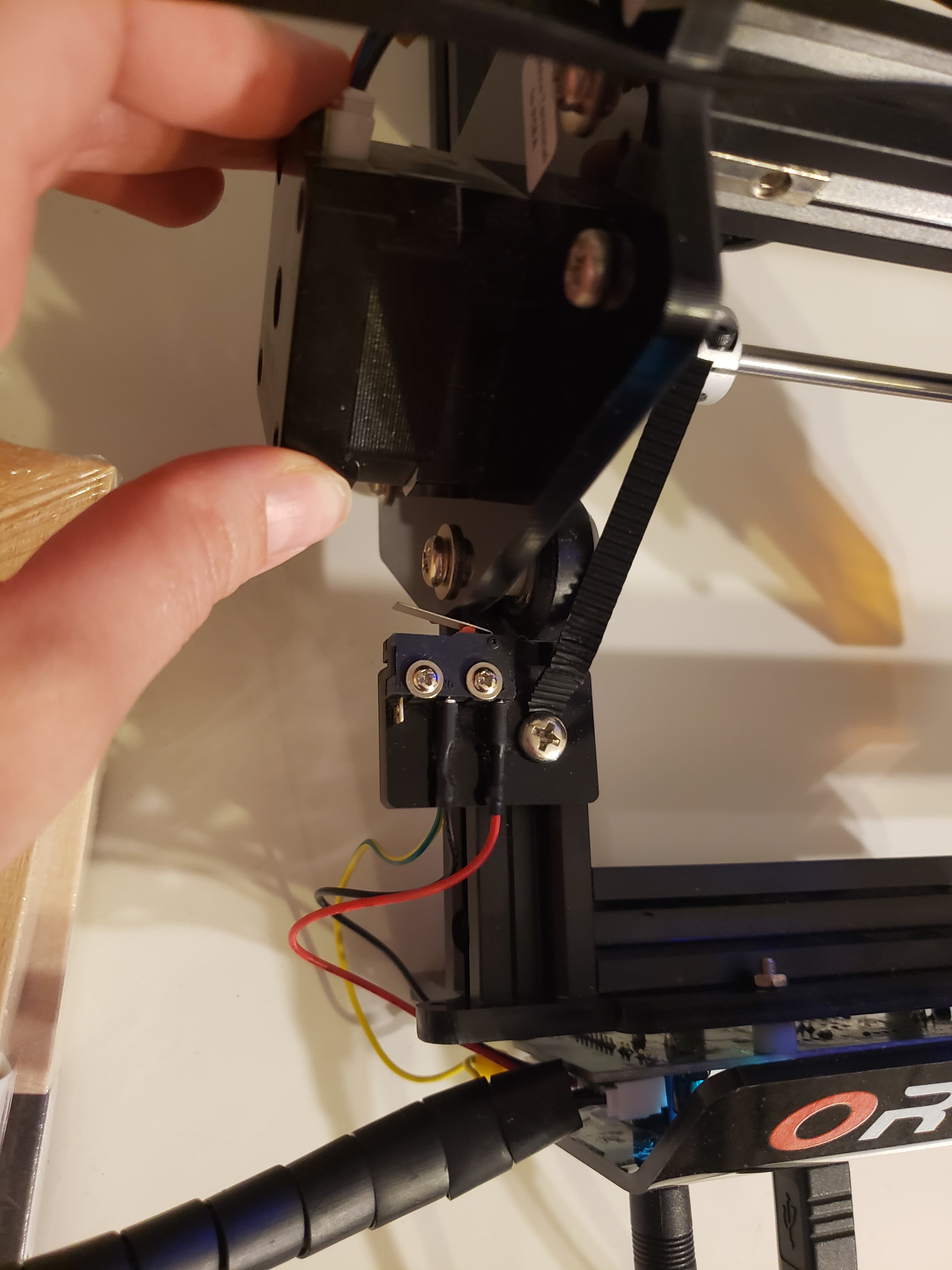
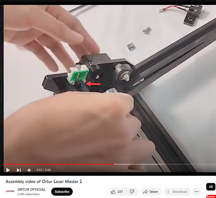
The Roller wheel on the right touches the bracket holding the limit switch before the gantry can move far enough to activate the switch.

Did your limit switch kit come with extra mounting hardware? If so, we may be able to put it to good use.

You may want to re-thread the belt under the lower forward roller wheel unless you’ve addressed a workflow concern by rerouting this.

Because the Y-Axis rail extends to the front edge of the engraver, you may find success in returning the belt to it’s original routing on the top of the rail, under the wheel, and installing the limit switch on the outboard side of the rail with a new Machine Screw and Tee-Nut so that the switch and the belt act independently of each other.

Once the switch is on the outboard side of the rail and not tied to the end of the belt you should have clearance to move the gantry fully forward and set the switch close enough to the gantry to activate it only when it’s at it’s maximum travel.

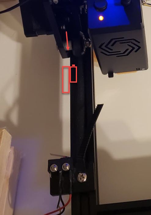
Here’s a quick sketch to clarify ‘orientation’ but not position. Mount the bracket on the outside of the rail with the new Tee nut and Machine screw. Then mount the switch on the inboard side of that bracket. Ideally the switch will contact the gantry on the vertical surface shown by the arrow and only when the gantry is at its maximum forward position.

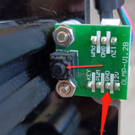
The switch may benefit from being turned upside-down from how it is currently on the bracket. Reversing the switch will allow the metal tab to behave like a little roof. It’ll help keep debris and dust (and sandwich crumbs) out of the switch.

Set the switch as far forward (close to you) as it will go on the outboard side of the rail and check to see if any of the fasteners that hold the rails together are interfering with the switch placement.

Slowly, by hand, pull the gantry all the way forward and hopefully the switch doesn’t click. If the switch clicks, tighten the machine screw holding the limit switch bracket and you’re done. If the switch Doesn’t click, move it back toward the (maximum forward) gantry until it does click then tighten the machine screw on the bracket.

Please report back and let us know if this solves it.

Also, this is the first time I’ve written about switch placement in any detail so if any of it is confusing please ask for clarification. If there’s anything that I can compose or change to offer greater clarity here please let me know.

You weren’t the first person to ask and I don’t think you’ll be last. :slight_smile:

Hello, thank you very much for your explanation. I did not change my limit switch but I’ve assured that my roller wheel does not touch the bracket before the gantry can touch it and activate the limit switch. Unfortunatly, It did not work. :confused: What tells me that it might be not the problem, it’s because I see my laser homing and I can see it goes right on my limit switch and it does a grinding sound even if my wheel does not touch it.
It’s strange because my laser engraving was doing really great before I installed my new module. Do you know if there were something that I missed to configure in lightburn software after installing the new module.

Because I just found two videos on Youtube with the same problem that is when the laser module goes homing, it does a grinding sound and in the end, doesn’t stop. In the two videos, they had two solutions, one change the info of homing typing $22=0 on the console then change to $22=1 and for him it worked. The other changed some parameter of the machine ( always in the Lightburn Software ) and he changed the Y step pin invert, the Y direction pin invert to false and the Y homing direction invert to true. And it worked for him that way. So I tried these two methods and didn’t work for me… :weary: I’m so desperate, I really don’t understand what is going on.

Your engraver may not be seeing the change in state of the switch. If this is what’s happening, we could expect that the homing behavior would drive into the limit switch and not stop and jump back 3 ish mm. (give or take)

None of this should be related to the module unless it’s physically larger and prevents the switches from being activated. If the switches are new as well, then that could be a missed setting.

If the switches can’t be made to work $22=0 turns off homing.

We’d look into this if the engraver wasn’t proceeding toward the switches.

Let’s get all the settings and see what we’re looking at. :slight_smile:

In the Console window in LightBurn please request the Device Info and Machine Settings reports by typing the following:
$i
$$
then press enter.

Please select that whole report and copy it from the Console window and paste it into a reply here.

One other thing we should check.
In the Console window type the following:
?
then press enter

Then reach over to your engraver and hold the X-Axis (left/right) homing switch in the active state. Use an elastic band or some masking tape if it’s too far to hold the switch and reach your computer.

With the X-Axis switch activated re-enter:
?
then press enter.

Deactivate the X-Axis Switch.

Activate the Y-Axis Switch.
With that switch active, In the Console window in LightBurn type:
?
then press enter.

Hopefully these three ‘Status-Immediate’ reports are all different and show the X and Y switch behavior. Please copy them into the reply here as well.

When we do stuff in the Console window, we’re talking directly to the engraver in a type of grbl based GCode. All of the ‘$ number equals settings’ are in the controller. Don’t worry about that. We’re pretty close to having this resolved.

Hello ! Here’s the first check up you wrote me to do. For the second check up, I did not really understand what to do… Well I don’t know the switches you’re writing about for the X and Y Axis. The switches that I know of are the switch that I’ve showed you in pictures weeks ago, like the homing switches hehe… Sorry for my ignorance on the subject. :sweat_smile:

Hope you’ll see something with this and again thank you for taking the time to help me with this.

[AUTHOR: ORTUR]

[MODEL: Ortur Laser Master 2]

[OLF: 142]

[DATE:18:41:30 - Dec 15 2021]

[VER:1.1h.210324:]

[OPT:VNZHI,99,512]

Target buffer size found

ok

$$

$0=2.000

$1=25

$2=0

$3=0

$4=0

$5=0

$6=0

$10=3

$11=0.050

$12=0.002

$13=0

$20=0

$21=1

$22=1

$23=5

$24=600.000

$25=3000.000

$26=100

$27=3.000

$30=1000

$31=0

$32=1

$33=500.000

$50=0

$51=0.000

$52=0.000

$100=80.000

$101=80.000

$102=80.000

$110=9000.000

$111=9000.000

$112=1200.000

$120=2200.000

$121=1800.000

$122=2500.000

$130=400.000

$131=430.000

$132=1000.000

ok

Yeah, it’s those switches. I’m glad that you said something. Generally, the X-Axis switch is the one that is triggered by Left/Right motion. The Y-Axis Switch is triggered by front to back motion (which is up and down on your screen). When you installed the switches, if you happen to have plugged the X-Axis switch where the Y-Axis switch is expected it can mess this up. The following test will confirm that the switches are behaving properly and installed correctly. :slight_smile:

Hello ! :slight_smile:

So I did what you wrote me to do and here’s what the console window wrote.


Since i don’t have a x axis limit switch, I only did it with the y axis limit switch. So I held this switch (see in the picture) and pressed ? .

I hope we’ll see the light beyond this and again sorry if I might have made you repeated yourself. English is not my native language and to me, all of this stuff is a little bit complex hehe. :sweat_smile:

1 Like

Excellent. So far, this test is conclusive.

The first status report shows no active switch.

The second status report shows an active Y-Axis switch.

The X-Axis switch is usually on the Gantry where the laser engrave head is.

To enable homing you need both X-Axis and Y-Axis switches. Because this device is configured for homing I went looking for the missing (and necessary) switch.

I checked out the Grounding Guide and the Assembly video and it appears that there’s a small button type switch behind the Gantry for the X-Axis.

If it is what I think it is the black switch isn’t mentioned in the diagrams and it’s pretty hard to see against the black rail.

Page 20 of the Grounding Guide makes this look a lot like a switch.
2023-07-03 forum 100866 laser master 2 Y limit switch on Pin board

Please press the round black button, confirm that it clicks and test this as you did the Y axis switch. :slight_smile:

Hello ! Thank for the explanation. I was not seeing the X axis switch before. So I’ve made it. Here’s what the console say. :slight_smile:

I think it doesn’t found the X axis switch if I compare what it said for the Y axis switch. :thinking:

Let me know. :slightly_smiling_face:

Ah-Hah! there is no PX in your report. does the switch click?
Do you request the ‘question mark’ report while holding the switch?

Well when I touch it, it click, but with the manipulation I came to see that the back of the laser engraver doesn’t engage the click. Here’s the reference in the photo.

And yes I requested the question mark while maintaining the X axis switch and the console said me this.

These engravers are designed to touch the switch. It should click. If it does not click something is preventing the motion.

I can see why. That little board with the switch on it, isn’t plugged in.

Have a look at the assembly video, starting at about 7:03 where that circuit board with the X-Axis limit switch gets plugged in.

This is a pretty good Blog post:

Here’s the Link from Ortur: Ortur Laser Master 2 – Ortur
Click Documentation,
Click Zip File, and download the manual.

Inside the Zip file (LaserMaster2.zip) will be a regular folder (LaserMaster2). In that folder you’ll find the User Manuals (including a French language one) which offer detailed assembly information.

This topic was automatically closed 30 days after the last reply. New replies are no longer allowed.