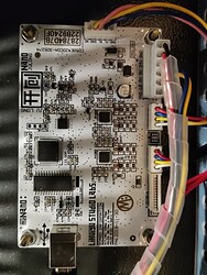
Hello Everybody,
I´m new on this forum and naturally have a problem with my upgrade of K40.
I am so sorry for my English, hope for You is understandable.
So, please if somebody have tip or suggestion for next step what I can do to solved problems.
Description:
I bought laser machine on links up. The plan was to gradually upgrade it to a better machine and during this learning new things. Everything what I am doing is only about hobby (I am interested in such issues) level for home use in my workshop.
First necessary thigs which were upgraded (to be more user friendly):
-
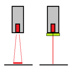
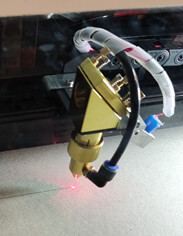
Red-Dot adjustment – only delimiter slot from hard paper
-
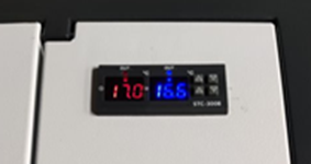
Temperature measurement of cooling water and laser tube. Two-channel panel meter with two temperature sensors and two AUX output relays for switching cooling and alarm. The AUX functions are not realized yet, now the module measures only temperature. At this moment it is enough to avoid critical temperatures.
-
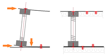
Axis Z table movement. From production was absolute terrible and inapplicable with corner error more than 5mm (moving table up was broken because of gear wheel spun). Everting was only about the construction modification. I Plan in the future completely new table, but now for the experiments is ok with this small improvement (now I have max 0.28mm gap between corners).
-
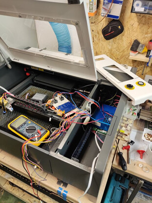
Motherboard change – this is main issue which I want to do, but some problems occurred and that is the reason why I am here to ask somebody for help.
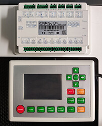
From production there was a M2 Nano and like a replacement will be RDC6442-S(BE)
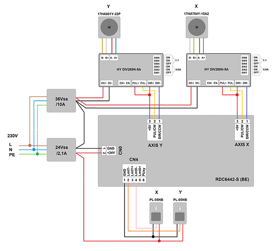
So necessary change with mechanical is done, let say little bit untypical because of lack of space. Also was necessary to added two news power supplies, one for the Ruida-Bord and second one for the drivers. Below is actual schematic diagram without connection to Laser tube. Now I want only be able to right setup (acceleration, moving, stopping) axes X, Y, after that rest connection to the laser tube.
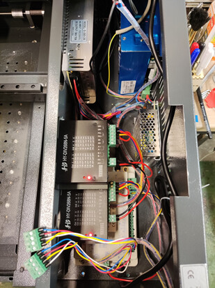
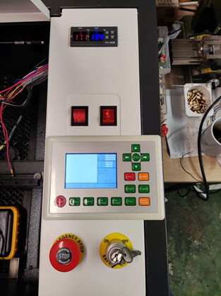
For setting of the RDC6442–S(BE) I´m using LightBurn SW. Here I have few findings. I am sure that for You are easy, but I am cannot move. Sorry for the stupid questions (I can’t rule it out), but maybe for other beginners will be helpful.
4.1) Setting of the step (um).
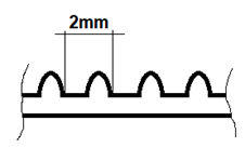
I don´t know if my formula is correct.
Step-motor 17HA704Y-15A2 has 0,9°. It means 400 steps for one turn. The belt has 2mm gap between the teeth. Number of pinion teeth is 20. So, one turn = 40mm (2x20). 40mm = 400 (360°/0,9°) steps without micro-stepping. When is the 1/16 micro used (driver HY-DIV268N-5A) will be 40mm = 6400 steps. Number of steps for the 1 mm is 6400/40 = 160, it means 1/160 = 0,00625 mm for one step. But when I used 6.25um like motor step, the motor is to loud and sometimes the engine jerks (quite better result was with the value about 5um, but it was only random experiment).
So my first question is how I can get the right value of the step? Must be the step value calculated with planned micro-stepping? When I used the 6.25um and the driver is set to 1/16 the motor goes really slowly to the end of axis.
That would be enough for an introduction
Thank you very much for help
JiF
