So I have some layers hidden and set to output off, yet they are being considered when determining the job origin. Is this normal? Is so, why?
Ver. 1.3.00 - 12/1
So I have some layers hidden and set to output off, yet they are being considered when determining the job origin. Is this normal? Is so, why?
Ver. 1.3.00 - 12/1
Seems normal. In that situation I need to goto cut selected graphics and set origin.
It may be the way the program is designed to work. I wouldn’t call it “normal”. It seems to me that stuff that is “hidden” should be just that - not considered to exist.
Agree with that. By normal I was referring to lightburn normal.
On a related note - after deleting the “hidden” stuff, I went to frame this and, to my surprise, it only framed one of the smaller boxes. Both tool layers are set to Frame. Is there rhyme or reason to determine what will frame?
Not sure of the tool layer framing, but you would have to think if it is not going to burn, it would not be included in the frame. So ya, not sure on the tool layer frame option.
As far as why you’d want output to affect the frame… I’ll offer an example.
Let’s say you have a complex circular design that you want to align to a circular piece of material, but then only want to engrave portions of that design at a time. Being able to include a circle as part of the design representing the outer boundary of the material is quite useful. Having that being used to frame the design but not output is actually quite useful.
In some ways the behavior and workflow is more natural on DSP machines that have an Origin button and using User Origin mode.
As for Tool layers, when you enable Frame button the tool layers should be referenced for framing. Is that not the case?
What you describe is very similar to what I was trying to do. I’ll try to explain…
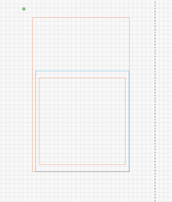
I was trying to design a jig and work template in a single LightBurn file. The plan was to first make a pocket in a piece of wood for the material (in this case, credit card bottle openers) and engrave a fiduciary marker to position the laser and serve as a reference.
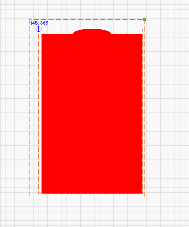
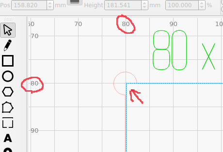
Then I would “hide” the outer tool box and the blue layer, leaving the the other tool box as reference for the origin and for framing. So, to run the actual pieces I would end up with something like this:
Except I want the origin to be the upper left corner of the tool box (where the fiduciary marker is). As you can see, it clearly is not. I ended up just splitting the file into two files to make it work.
When I went to run some pieces I discovered that the tool layer was serving as an origin reference point but was not being included in the framing.
I hope this makes sense…
You can use ‘cut selected graphics’ with ‘use selection origin’… to modify where the ‘origin’ is located in the software.
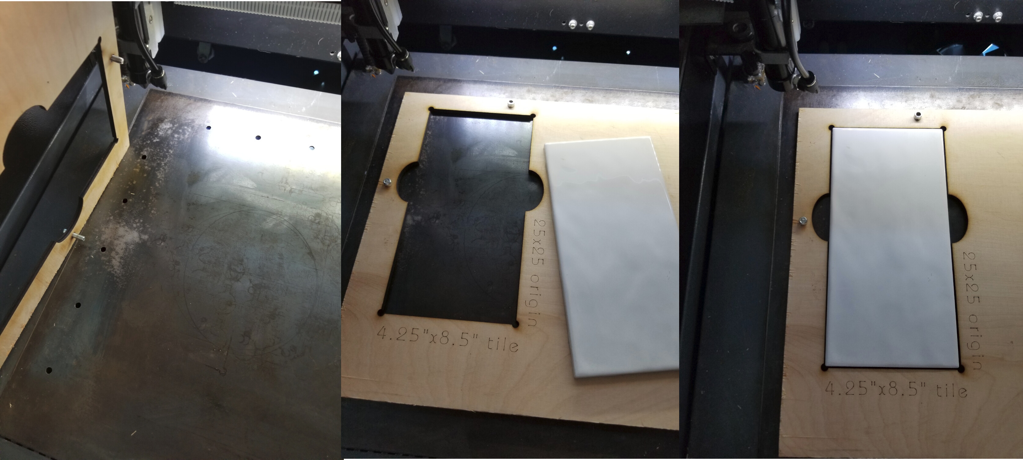
I have a similar setup for doing tiles, coasters, mirrors and such…
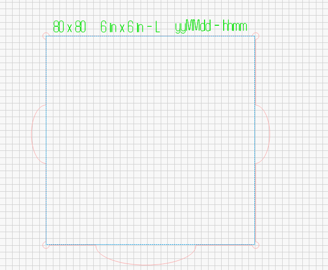
I ‘cut’ the screw holes in the template. Put in screws and re-place it into the machine. Now using ‘absolute coordinates’ cut the objects hole in the template. I have the corner set to whatever my ‘absolute’ origin is on the work area… In this case it’s 80x80. I have to point out that you can do this with the machine origin set to ‘80, 80’ using ‘User Origin’ I’ve found less errors using the absolute coordinate system for the original template.
I always label them, date/time of creation and specify an ‘origin’ This 6x6 is one of three, L is a manufacturer as all of these tiles are not 6x6, at least they won’t fit in other 6x6" templates I have and use. ![]()
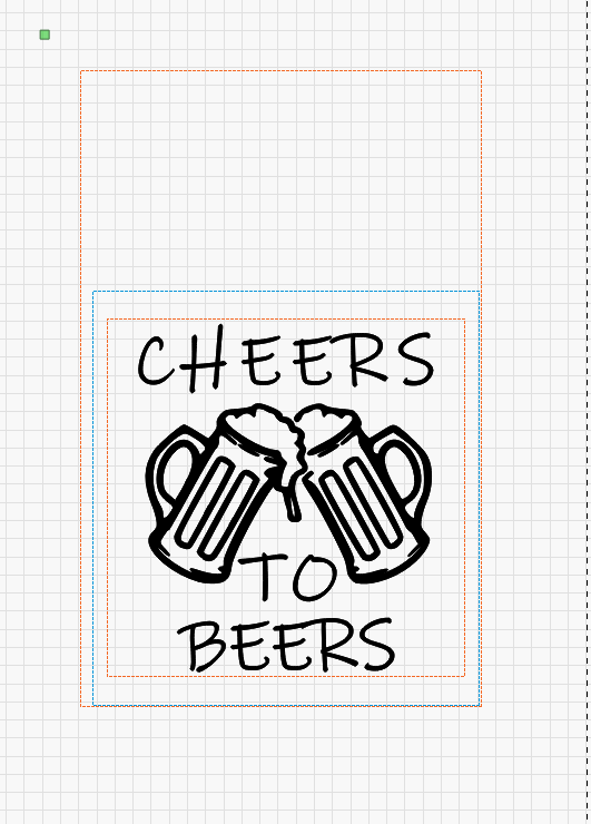
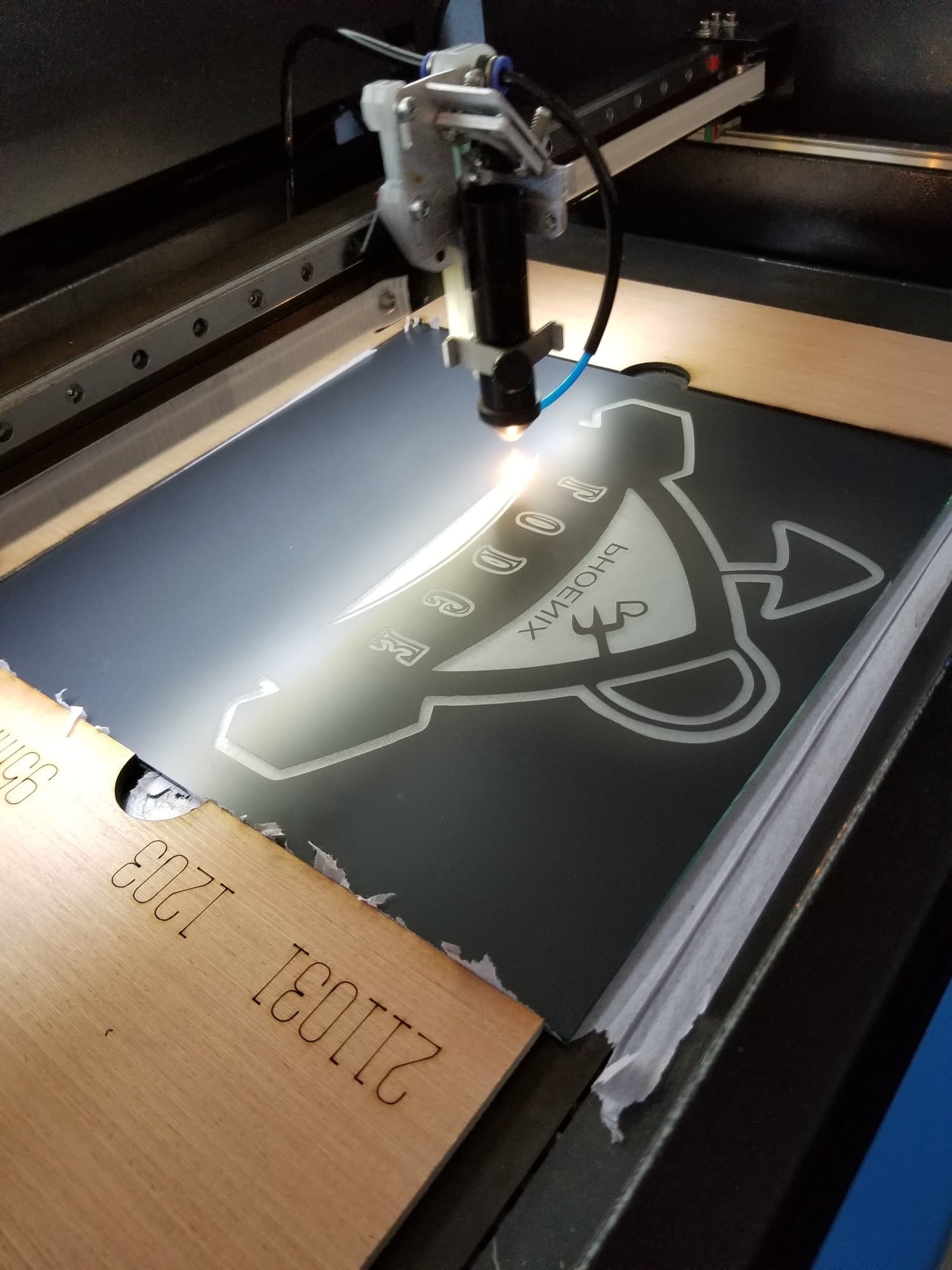
This is a different template, but the idea works fine… red is the cut template outline, the blue is the tool layer where the art will be ‘aligned’
You can import the template or just draw another tool layer for alignment.
12" sq mirror (back)…
I tend to do the alignment or creation of the template in absolute coordinates and many times will set the ‘origin’ of the machine to 80x80 and run it with ‘user origin’ selected…
After all, it’s all relative ![]()
6x6inch-tile-L-brand.lbrn2 (73.9 KB)
This topic was automatically closed 30 days after the last reply. New replies are no longer allowed.