I just fired up my new Chinese 60watt laser, set the lightburn parameters, and homed the machine. I assumed that top left should be the home position but goes to top right even after setting the home position to top left. The axis control moves correctly, but the display says I’m moving in a positive direction when I’m actually moving in the negative direction. Is there a problem or is that the nature of the beast?
My 60W Omtech laser homes to the upper right. No problems.
Thank you!
DSP controllers home to wherever the homing sensors are, so the position will vary between different types of machine.
My machine homes top right, but I work primarily from top left. It works out great as I have to use different edge guides for different materials. I could physically hit the edge guide in some instances if I didn’t pay attention and homed into a tall guide piece by accident.
That makes sense…im going to ‘borrow’ that idea and put it to use. I’ve been messing around withe the new 60w laser all afternoon. It is a HUGE difference from Ortur 20w. Each one will have their purpose, though.
That’s one hell of a jump. With the proper configuration, you can cut 1x6 clear pine with that 60W and not have the black charred edges.
I just made a brontosaurus jigsaw puzzle using 1/4" plywood for my almost 3 year old grandson…the 60w cut it like butter with no charring or staining. Im going to have a lot of fun with this.
Yeah, a 60W should have no problem with 1/4" ply. Not sure about Premium MDF, but it should be close. Be careful if you get material from the big box stores. The inner layers pf ply can have voids and adhesive bubbles, and the occasional metal flakes can crack a lens. The MDF you get there is LOW quality, and nasty resins.
Do some searching for Premium MDF, sometimes called double refined, in your area. The high end lumber yards and hardwood suppliers can give you pointers on where to get it if they don’t carry it. 1/4" and thicker Premium MDF can be from about five suppliers if I remember. I have only one supplier for the 1/8" in the US, Weyerhauser.
We have a few lumber yards in this area so hopefully finding decent materials won’t be a problem. I see what you mean about the box store ply . While it was being cut I saw variations in the depth and some flashing/sparkling…exactly what you described. It was a leftover piece that I had laying around to try a few things.
I would think the biggest change you are going to have to get used to going from a diode to a CO2 is the air assist and focal length and what that entails. Add in that most sub 100W machines are shipped with an engraving set up instead of a cutting set up, and it’s a whole new world to navigate.
Switching from and engraving to a cutting set up gets you an automatic rough 40% jump in cutting capability. Add in a long focal length and good air assist and you can roughly double your effective cutting from the engraving configuration you started with. It’s all in the lens tube and nozzle.
The one thing I do have to correct is the tram… it is cutting at a very noticeable angle. Any words of advice?
Not sure I kn ow what you are talking about. Do you mean your X is not square to your Y, or your Z is not square to the cutting bed?
When I make a cut…a square for instance…the opposite sides are parallel, but not perpendicular to the bed surface.
Okay, that’s called a skew error. Here’s the procedure I got from Russ’ videos.
Set up as large a rectangle as you can safely cut. Use paper, I used old wrapping paper. In making the rectangle, put a dashed line down the center. Once you cut it, fold it on the dashed line, the amount the corners don’t match is roughly how far out you are. You will have to add a bit to compensate for the paper dimension vs. the full length of your X axis.
Now comes the fun part, and it’s purely physical, not anything in programming. You have to physically move one end or the other to get things square again. I lucked out in that my skew error was almost exactly a belt tooth. I had a 2.7mm skew, and a 2.5mm belt tooth spacing. I loosened one belt, hopped a tooth, and tightened it back down. I have at least a .3mm kerf, and I very rarely do interlocking pieces, so I could live with a .+/- 2mm skew.
If you don’t get that lucky, then you will have to loosen one of the toothed gears on the end of the Y drive shaft. That usually involves a nut and two set screws. You’ll need two good clamps, and something the thickness of your adjustment amount. On one side you put the clamp up against the gantry, I think you called it a tram. On the side you need to adjust, you put the clamp on, but with the spacer.
Loosen the side you put the spacer on, pull the spacer, and make sure both sides are now up against the clamps. Tighten everything down and retest.
It’s not difficult, but you may be discussing the heritage of the engineer that designed that thing in getting to the Y drive shaft end. I had one buried under the laser tube against the Y drive motor, and the other a bit more accessible, but right by the #1 mirror.
I’m not sure we are talking about the same thing. I will upload a pic of the piece a bit later…dealing with a sh–load of snow this morning.
No problem.
Here is a close up pic of the problem.
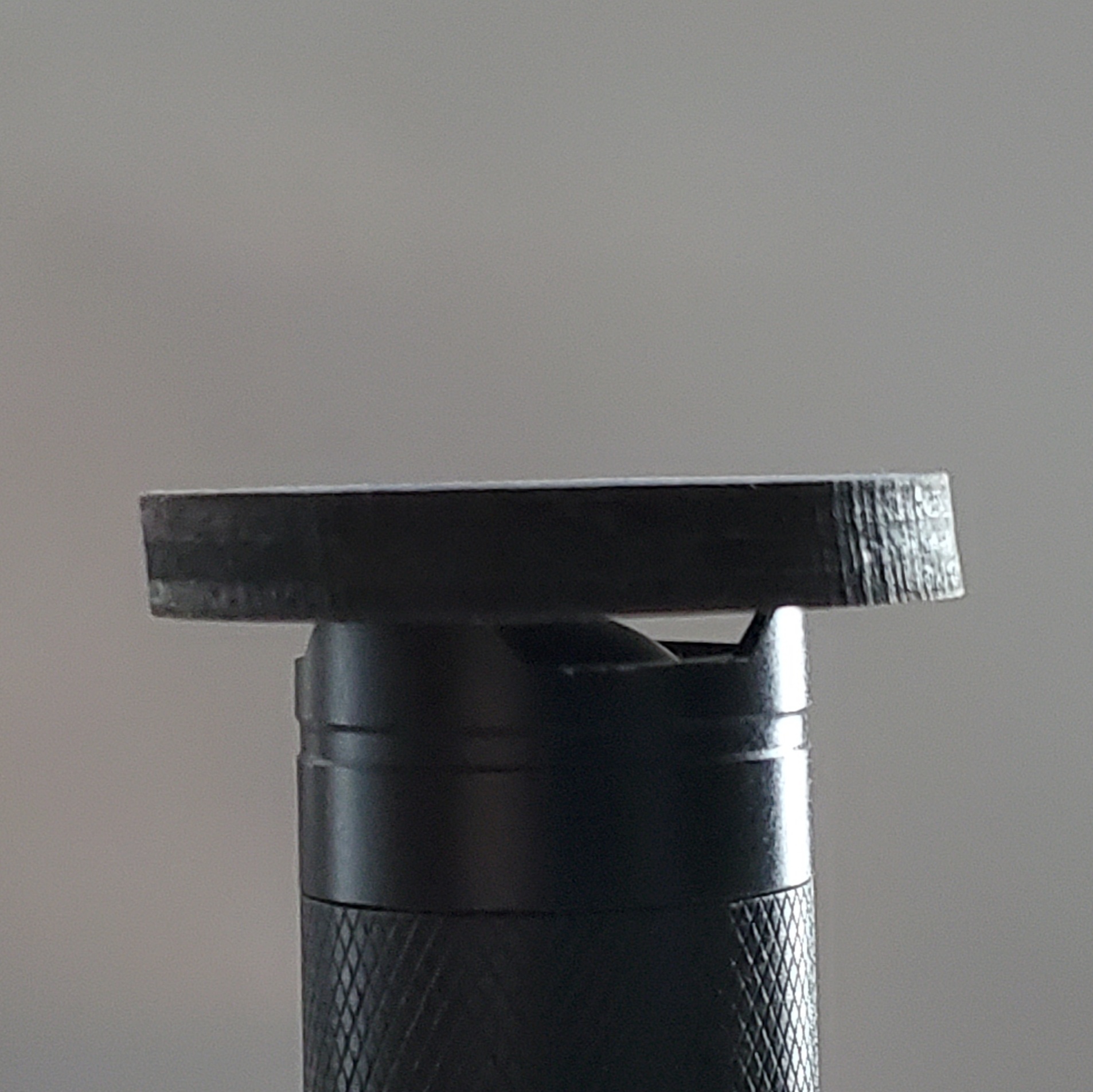
See how the left and right edges are parallel but not 90 degrees to the surface? The piece in the pic is sitting at 45 degrees so I’m assuming that it needs adjusted on both axis.
Somebody correct me if I’m wrong, but parallel slant on opposite sides is a Z issue. Either the head not parallel / square to your bed, or not hitting the lens on center. If it was a trapezoid I’d say short focal length, but a parallelogram says the beam isn’t hitting the work square.
When you do an alignment and lower the bed to check Z, does the spot move? It shouldn’t, but I have to ask to further diagnose.
Yeah, that looks like the laser is not perpendicular to the work surface… IE: not pointed straight down.