How do you join lines into a closed shape?

So, I’m having way more difficulty than anticipated making shapes in LB.

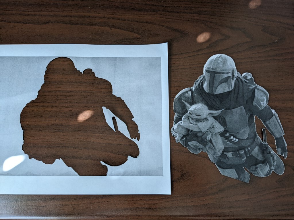
This is a trace that was “mostly” usable. There were internal shapes on light things, but I just deleted those. But I used the Line tool to make some patches to the final outer trace. I selected all of it and did a Node Edit which turned out to be a painfully tedious process to trim into a single continuous line… I need to make this into a closed shape and I can’t make it work.

But now it’s not interpreted as a single continuous line, and I can’t make a closed shape out of this. The lines created in random order and direction are retaining that order and direction. The Close Path won’t work because it looks like it’s only considering joining loose ends created subsequently in time, not proximity. “Close Path with Tolerance” will not try to join even coincident endpoints with any tolerance- if tolerance is increased, it will attempt to join unrelated segments far away rather than the coincident endpoint of another line.

It’s not a shape yet, so Auto-Join Shape and Optimize Shape shouldn’t work. Auto Join doesn’t, but Optimize actually does seem to work on it as a line simplifier, but it’s not going to make a closed shape.

Nothing seems to close it. I did discover some TEENY spots where lines overlapped but nothing would repair that automatically- found them via Preview window and saw the red rapid-transverse jumps. Now I’m still got a few rapids jumping to different start points and I can’t find any feature at that point to repair. “Close Selected Path With Tolerance” attempts to repair it and still thinks it’s 6 open shapes.

Am I missing some key points of the design flow, or is there a bug or what?

the-mandalorian-14-din-grogu.lbrn2 (357.6 KB)

I looked and you have line segments that overlap and overshoot.

trim / extend might be the way through for you.

I wrote a fairly thorough post describing how and when close path as well as close path with tolerance will work. It also covers auto-join select shapes and how it differs from close path.

Might be worth a read.

1 Like

OK. So I experimented more and I think I see the problem situation here. LB’s handling has some weaknesses that can be improved, because manually repairing can be a nightmare on complex shapes and the methods to auto-fix are logically possible.

First off, we’re being inconsistent on terms. “Vectors” is unambiguous, but “Path” and “Shape” I’m unclear on what LB intends for them to mean. Part of this is so I can teach LB. This goes much smoother when we stick with established terms that we use consistently.

I believe “Shape” would refer to a simple closed shape. It is essential to be closed for “kerf” to work, as it must have an inside and outside. An example of a closed shape that is not “simple” would be a bowtie of 4 vertices and 4 vectors. Technically enclosed, but will break many algorithms for handling closed shapes as the concept of inside and outside may invert when the vectors cross. It’s not valid, sure, but not hard to create by accident when building a shape by hand.

So, first off I built a shape with lines snapped “for sure” on common vertices, but NOT done in order, nor even a common direction. Sometimes segments drawn clockwise, some CCW. Some drawn between 2 new vertices and then joined up to other vertices with another vector later.

“Close Path” will fail to turn this into a closed shape, even though it already is a closed shape (just not officially as a software construct). What’s more, it does it silently- there is no feedback that it failed to close.

“Auto Join Selected Shape” will fix this and create a closed shape. Point of semantics confusing our people though- this does not work on a “selected shape”. We select vectors that must already form a closed path that was not yet officially structured as a closed shape, and then create that closed shape.
It WILL have an effect on complex closed shapes- the bowtie. But the result is probably not a good thing.
Now consider what would happen if we have a bowtie- 4 vertices, 4 vectors, which makes 2 triangles but no vertex where they cross in the middle. Delete the straight, non-crossing vector on one side. There is now a closed triangle where 2 vectors cross but continue on and LB sees no vertex there so it will not see this as a closed shape. Auto Join could still work, but will fail (without any feedback), and it cannot be fixed by anything but manual editing.

The bigger problem is trying to join up vectors that have nearby vertices, but not coincident. Auto Join cannot be used. Here’s where we have a show-stopping problem: LB only evaluates vectors in their creation order and creation direction, data which is not apparent in the tool, and essentially irreparable as far as I can see. Also illogical as we don’t think of vectors as defined by order and direction.

So, the “Close Shape with Tolerance” would work, right? Well, here’s LB’s bug: it will fail, because LB can only join in the creation order. Enclosed is such an example, where vectors were created in nonlinear order and direction, but should still be closeable with a tolerance. It will fail, however, and produce a perverse interpretation that is more broken than the original shape.

uncloseable_shape.lbrn2 (8.8 KB)

I did learn how to “repair” it in LB and rebuild as a closed shape. It seems like an exceedingly difficult manual process compared to modern tools (Photoshop, etc) where you can just start with a selection from Magic Wand etc that inherently will always be a simple closed shape (one or multiple shapes anyhow) and any adjustments to add or subtract from it will also inherently remain a simple closed shape(s).

I do see the better option might be to use Gimp to do selection, create a transparency mask, and resave the bitmap. LB’s trace should be 99% accurate following the transparency mask. However, like in this case, I’m using the corners of the printout as Target 1 and Target 2, and using the transparency mask might eliminate these corners. But now that I think about it I could just invert the selection and make the part we’re saving the transparent hole, so only the area around the image and its fiducials will show up in LB. LB doesn’t functionally need to see that image, only the closed shape around it. It does make some sense.

1 Like

Separate issue- can anyone try to actually do this as a Print and Cut? Because when I ran this either as the “broken” path that was not a closed shape, OR the “repaired” simple closed shape, selecting the bottom left and top right corners as Targets and Align With Scaling and sending to the machine consistently gave the wrong results. The cut was shifted about 1/2" from where it should be. ONLY this project, I was successful and accurate with 3 prior jobs. I quit LB, reloaded, reset the Targets, tried again from the top, EXACTLY the same P&C error. I went back AGAIN and recreated the outline all over again from Trace, but still got exactly the same error.

I don’t know what’s different here that breaks P&C for this one, but there it is. The only thing that comes to mind is the others I used top left/bottom right for targets, this time I used bottom left/top right.

Ran the Print and Cut without too much trouble. In fact, did it twice because I undercut the first time around. Print and Cut got the 2nd pass admirably close. I still managed to undercut so excuse the tearout.

My bad I referred to the wrong Mandalorian project. This one is the one that fails P&C due to a strange offset. I even redid it with a new Trace and patched the trouble spots and manually ensured it was a simple closed path, but still offset. Just this one file. Give it a try if you can and see if it breaks anyone else’s system

mandalorian-the-tragedyc.lbrn2 (520.5 KB)

Worked out about the same as the last one… No specific drama. Forgot to mention the last time but I did have to scale both of these down to letter size paper so that’s a variable.

Interesting. I can’t make this job P&C correctly and still no idea. It was printed on a standard 8.5"x11" laser printer on “fit to page”, so it shouldn’t need to be rescaled. Well, you don’t rescale anything in LB. If the bitmap import makes it 20" wide, we still have no reason to rescale inside the LB workspace as P&C is already going to do that. The size inside the workspace should be irrelevant, but mine was scaled as 12.4984" x 8.3323". I think I’ll try rescaling as part of the debugging, maybe something about the ratio broke P&C’s math??

Hey, yours is mirrored. Any idea why?

Different machine origin configuration on my machine than yours. I figured there would be a chance that it wouldn’t match but wasn’t sure what yours was configured to so didn’t try to correct for it. I did this on an Ortur LM2.

You’ll need it to scale at some point. Either you use P&C with the scale option or whatnot. In the case of the print you had your printer do the scaling of the raster. You’ll need P&C to also scale to the printed dimensions.

Or you scale the image and outline in LightBurn, print to 100%, and then P&C without scaling.

At some point everything will need to agree or else you’ll get something you don’t expect.

I’m saying it’s a natural instinct to assume that when you bring the image into the workspace it needs to be scaled to the printout. But that would be redundant for P&C, as it will do that automatically as long as you don’t select “No Scaling”. P&C won’t care if your image is imported larger or smaller than the actual printout, as long as it fits in the workspace, image scale is irrelevant.

Got you. Where it does make sense to scale the image in LightBurn is if you actually care about the end dimensions.

I am not sure I understand what RalphU is saying. Sounds like he manually traced the edge of the image, which I admit may be the best way, although somewhat time consuming. I think the original post is asking why the Trace function cannot provide a good outline image without a lot of tedious post processing work. Honestly, I gave up on the Trace command and usually trace the image in a separate file where I eliminate the background portion of the image as well. So what is the Trace command good for?

Trace is “perfect” if you download a black and white image online. Many things you find are called “vector art” but are actually in a bitmap format (bmp, jpg, etc), not SVG/DXF etc vector file formats. Like, the image may be literally black and white, no grayscale, but it’s still a bitmap.

If you need this to be a vector for cutting or to do a Fill or any processing that requires vectors, then Trace is a no-brainer.

It is not as sophisticated as the Photoshop “Magic Wand” for selecting things on a photograph. LB does not have the resources like Adobe has to build that sort of advanced code base right now. Using Photoshop (or freeware Gimp) outside of LB to make a transparency mask or turn into a black/white block mask is an option.

I’m not sure if this is what you are asking, but sometimes when I’m in node edit mode, I can’t seem to force two line ends to join to become a closed shape. I found that if you toggle on the “snap to objects” under preferences, and drag one end point onto the other, the two end points will join into one point and close the shape. Sometimes I have to do it twice if it doesn’t join the first time.

This topic was automatically closed 30 days after the last reply. New replies are no longer allowed.