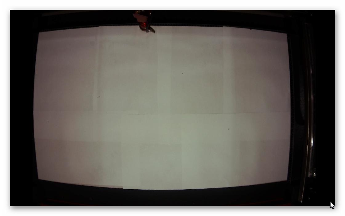
I have an 8mp ELP camera with effectively a 70 degree lens mounted to the lid of my BOSS 2440. It provides a clear image of the white paper covered bed plus about 1 inch of extra around the edge.
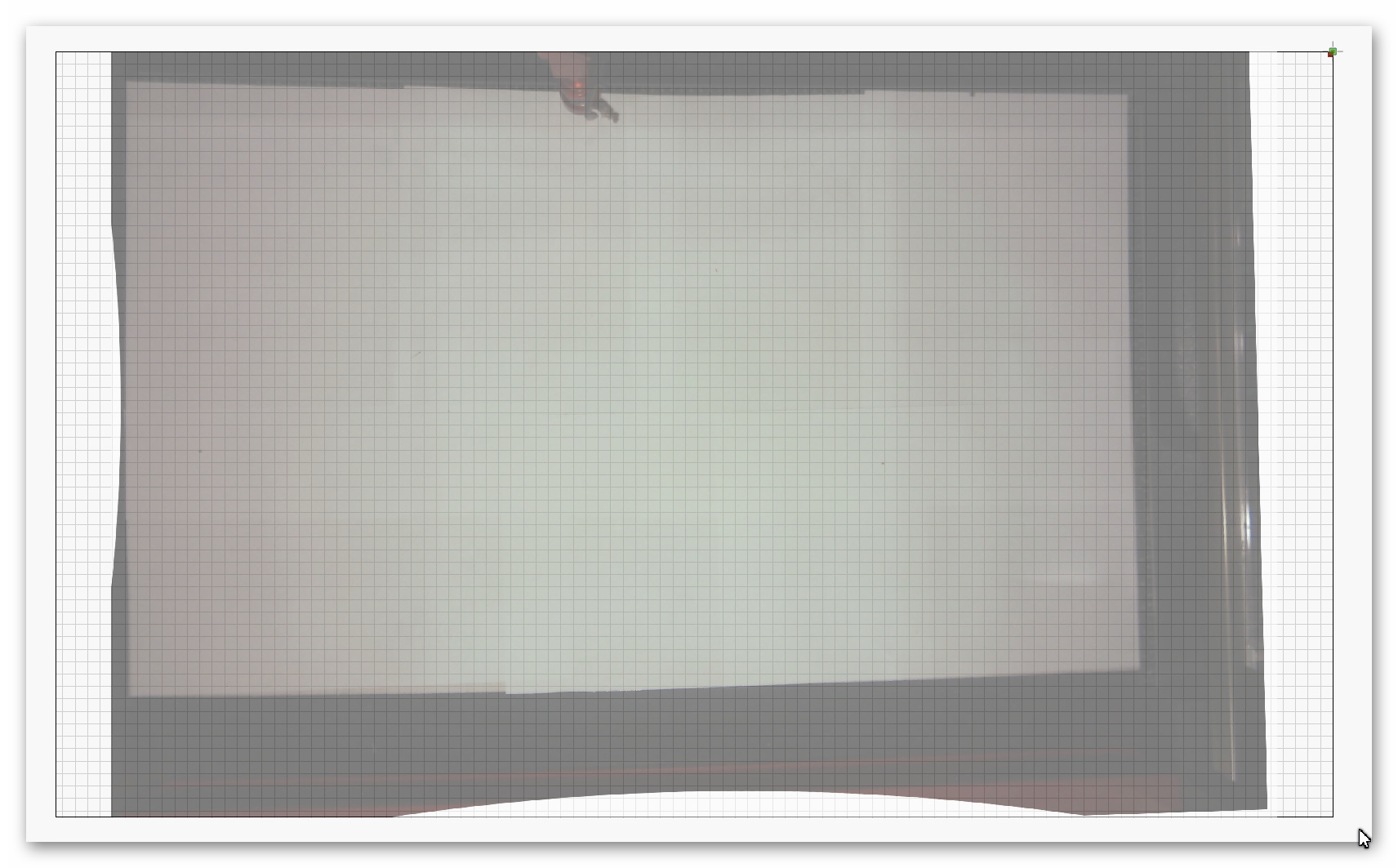
I tried to calibrate in both the standard and fish-eye lens settings and I get similar results. The overlay is too small and is distorted. I have attached pictures of each. Ideas?!
Your camera is a fish-eye lens, so use that option when calibrating. Did you also do the alignment calibration, or just the lens calibration? You need to do both before the image will be accurate.
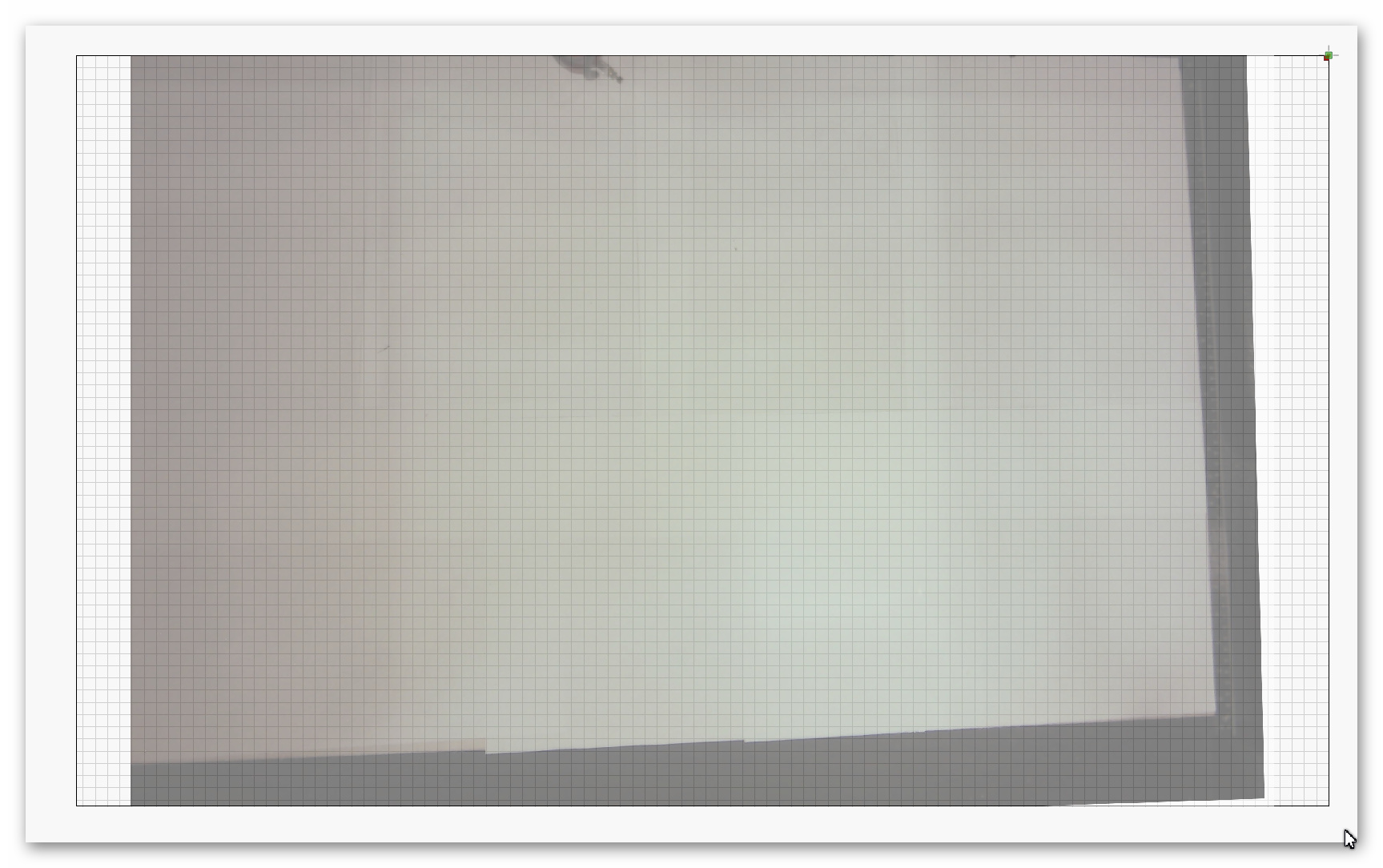
Since it happened not to be convenient at the time, I indeed did make the mistake of stopping before doing camera alignment. I hadn’t done that before so therein was my confusion. I started over from scratch using a fisheye lens setting and I had to click and click to get usable results but also got to a point where it wouldn’t capture anything that would pass. I started over using a standard lens setting. I consistently then got values in the .15 to .3 range. After that I did the camera alignment and here is what the resulting overlay looks like:
When you did the lens calibration, was the pattern filling roughly 1/3rd of the view horizontally & vertically, as shown in the tips here?
The most common thing people do is lay the pattern card on the bed and run it from there, but the lens calibration part has nothing to do with the laser, just the camera and that card.
Using the fisheye option should give you slightly more usable image, because it doesn’t discard the stuff that’s clipped because of the warping.
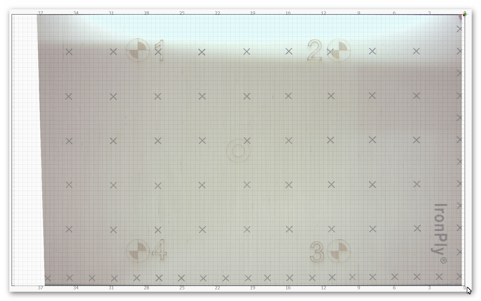
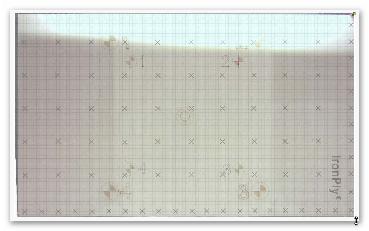
Thanks for the insight. I started over with a larger circles image and really paid attention to lighting. I found it to be very fussy. I used the fisheye setting and tilted the circles pattern so it remained more or less rectangular in the camera image. Most of the images were about .20 or less but some took several clicks to get there. Once calibration was done I did the alignment and this is what the overlay now looks like:
(The burnout in the image is due to the LEDs on the horizontal gantry.) As you can see the overlay is nearly perfect. I burned a dot at the center of each target and they are “spot on”. It was a learning experience. For me, lighting and keeping the image rectangular in the camera view made all the difference.
It is fussy, and unfortunately there isn’t a lot I can do about that.
I have written quite a lot in the documentation about how to do it and what to watch for, but most people plow through without paying much attention to that, so more words aren’t likely to help.
Your results look great - glad it’s working for you now.
It really is any amazing capability to be able to overlay the image of the laser bed/stock onto the drawing surface. It really is worth any amount of trouble it takes to get it set up. Thanks for your hard work!