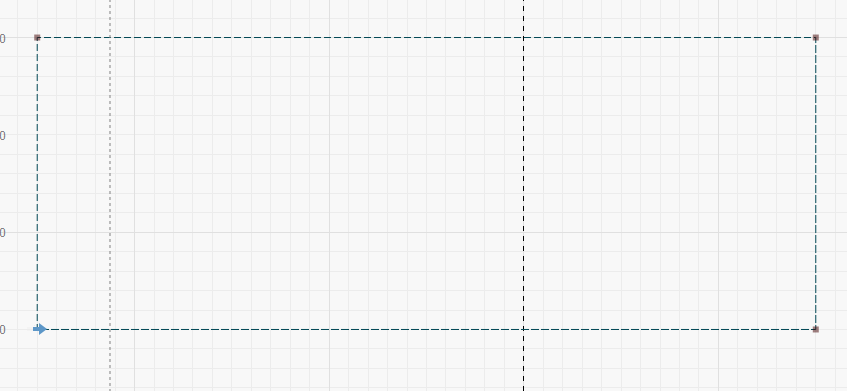
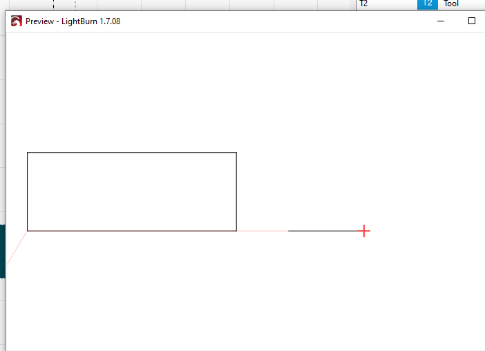
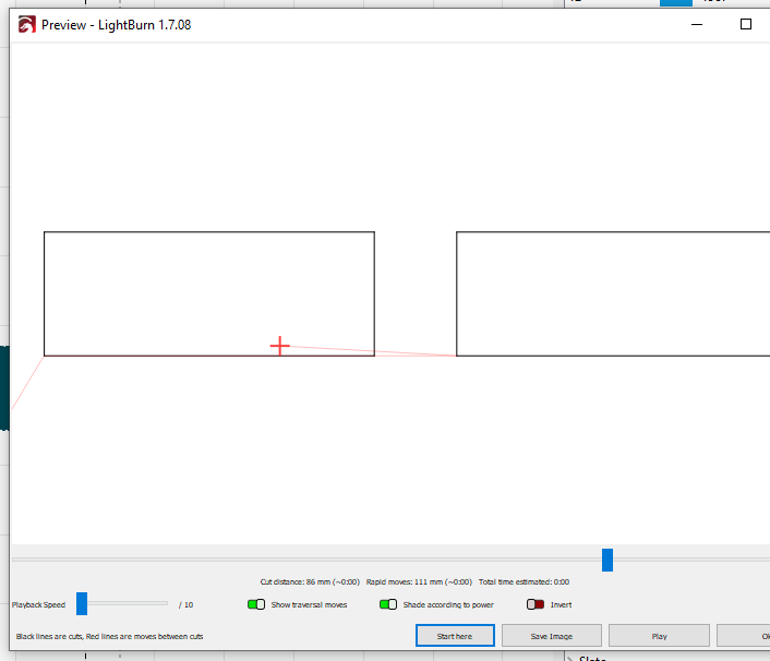
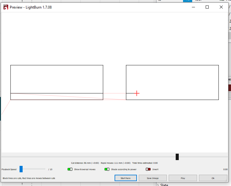
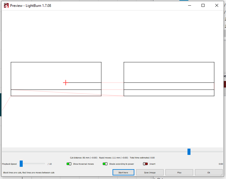
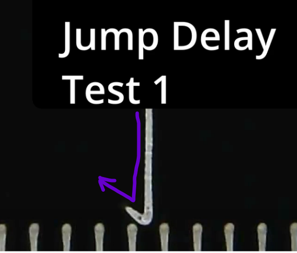
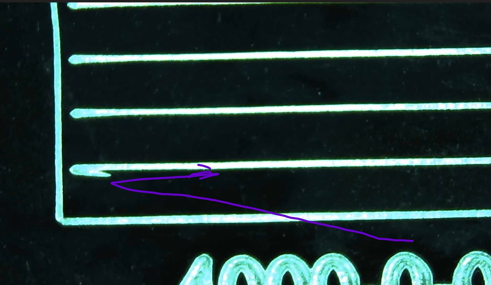
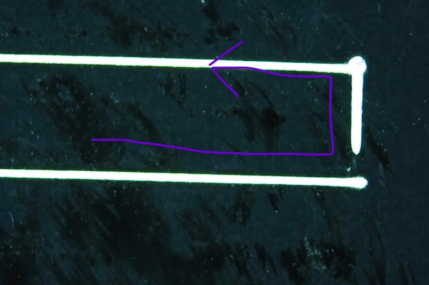
Another thing that’s bothering me- I’ve been focused on raster. Let’s think vector. Let’s say it’s a 90deg corner. The POLYGON_TC says after it burns from x0, y0 to the commanded coords X1, Y1 and waits POLYGON TC while the beam stays on (AFAIK). So it didn’t do “try to jump to X1, Y1, but just keep driving there until you coast past, then brake”. The overburn would show the beam overshooting the corner, then make an overlapping line as it moves back to X1, Y1 and waits before it heads on on the second side.
So, the BJJCZ does have an idea of how to initiate a brake ahead of reaching X1, Y1. How does it know that?
Well, it doesn’t actually know when it’s reached X1, Y1. If POLYGON_TC=0, it will round off. POLYGON_TC is NOT about turning off the beam at all. It doesn’t even involve the beam.
OK, the bjjcz is told “jump to x=0,y=0 (beam off), fire to x=0 y=20 at 3000mm/sm, then fire to x=20, y=20”.
So if the mirrors are like a voice coil against a spring, the analog DC current sets a static point of deflection it will eventually rest at. The bjjcz could calc that current and blindly drive it with a DAC, and calcs “20mm of motion at 3000mm/s is 6,666us. So just tell the DAC to move from (0,0) to (0,20), wait 6,666us, then tell the DAC to move to (20,20)”
But acceleration must happen. It’s not at 3000mm/s for the first half mm or so. So they revised it to “tell the DAC to move from (0,0) to (0,20), wait 6,666us PLUS dwell with the DAC target at (0,20) for a user-specified POLYGON_TC, then tell the DAC to move to (20,20)”
That would require no additional calibration inside the bjjcz. But if that’s what it is, then the time dwelled for POLYGON_TC would be excessive when running lower speeds.
I can test for that. But, what if this isn’t actually a fixed time constant? The dwell time needs to scale with speed. But the bjjcz was told the speed. It knows it. It probably DOES scale POLYGON_TC by speed… in which case, it was never really a “time constant”. If so, POLYGON_TC=100us never actually meant 100us. Nor is it a distance. It’s an acceleration factor.
So the code would be:
fire from x0,y0 to x1,y2, then fire to x3,y3. segment distances are precalculated as vector sums v0 and v1. vo=sqrt((x1-x0)^2 + (y1-y0)^2)
is
“if LASER_TC is negative, set LASERON=1, wait LASER TC”
“now set DAC=x1,x1”
then
“if LASER_TC is positive, start a countdown from LASER_TC_ON and fire the laser when it reaches zero” and simultaneously "start a countdown timer at LASER_TC_ON and fire the laser when it reaches 0. and "start motion countdown timer= “(v0/SPEED plus POLYGON/TC*SPEED)``" for the mirror to reach what we assume is x1,y1. then once the "set DAC for x3, y3" and "set countdown timer for ((v1/SPEED plus POLYGON_TC*SPEED)-LASER_OFF_TC))`, turn off laser when it reaches zero”. That would mean larger LASER_OFF_TC turns the beam off sooner. This is the way the sign worked in my testing.
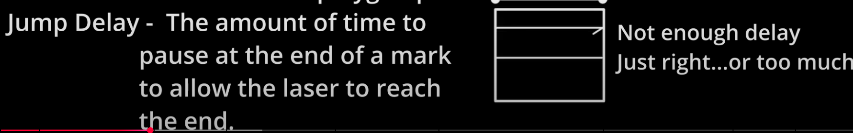
END_TC would apply to x3,y3 somehow. Does it control how long the beam stays on? I don’t think so. Sounds like it replaces POLYGON_TC if the cut vector is followed by a JUMP instead of chaining with another vector.
So my guess is POLYGON_TC and END_TC only affect the motion part. LASER_TC_ON and OFF only apply to the laser fire command