I’m new to laser engraving and trying to get my machine all dialed in. Have a Creality Falcon2, running Lightburn on my Mac. Not having any obvious software problems, but I saw the ‘Dot Test With Angle’ suggested for checking calibration. I’ve downloaded that and burned it a couple of times.
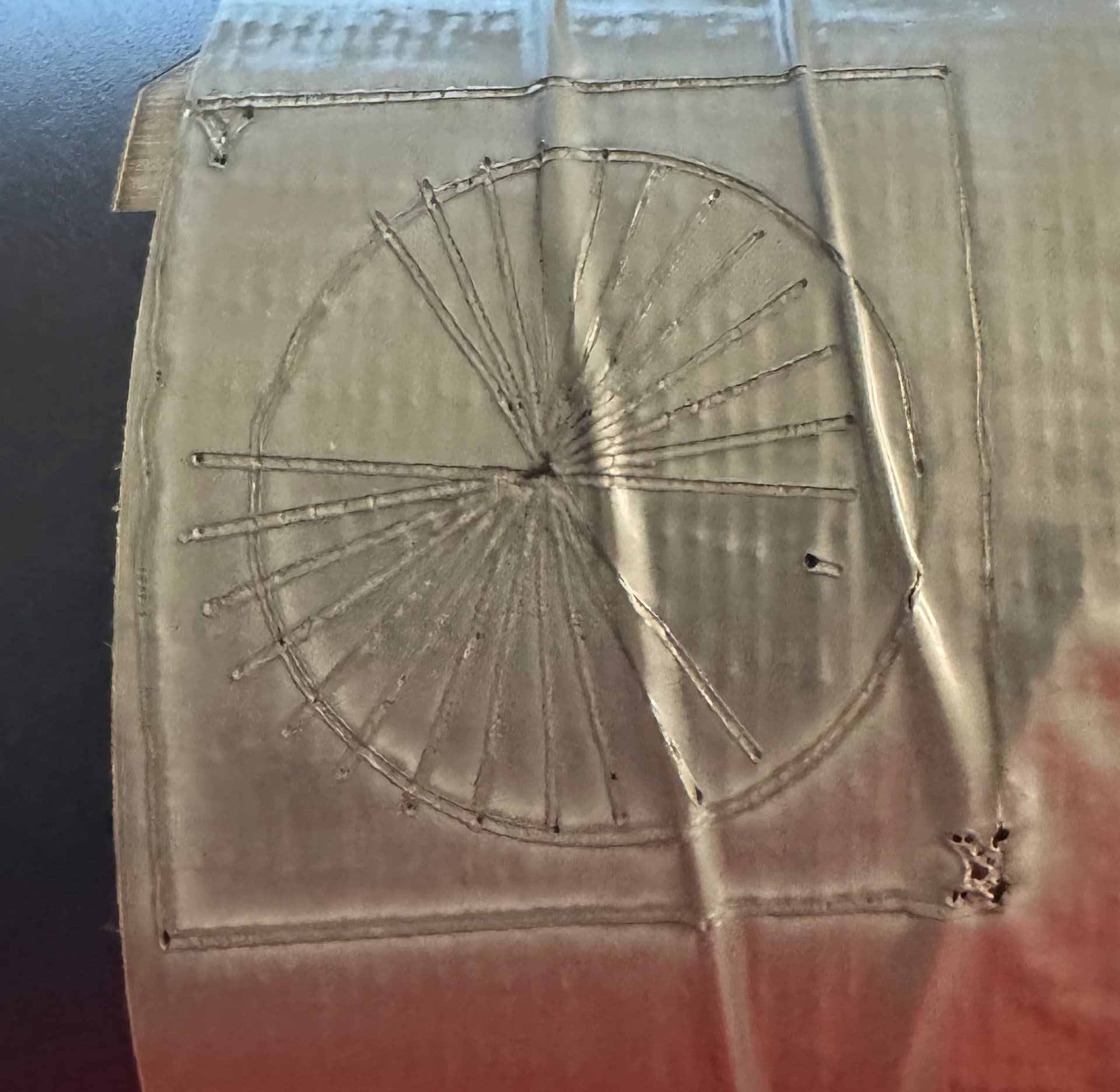
The square and circle seem fine, but the straight lines inside the circle aren’t lining up. They are shifted out of the circle some - see below.
Can anyone tell me what might be causing the misalignment? The crappy application of the layer of duct tape isn’t the cause, it does that on the bottle itself just as much. Thanks in advance!
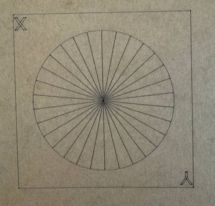
Where did you see this? Can you attach it here for reference. It’s not readily apparent what the reference is for this.
It’s hard to get a real sense of what’s going on. Some of that may be due to the duct tape. Without knowing the reference design here are some things I notice:
You likely have some mechanical issues with your machine. Neither horizontal or vertical lines are straight. This may be from general looseness, malformed wheels, or perhaps from being overtensioned. I suggest you do a full review of the machine to make sure there’s no slop in the machine and that things are properly tensioned
I’m going to assume that the rotated lines are meant to be centered in the circle. If so, you’re losing motion somewhere. This is most often caused by overly loose belts. They should not have any visible slack and taught but not stretched.
Once you review rerun the test on a cleaner surface and circle back along with the attached reference test.
Thanks for the reply! I’d found this pattern for testing the machine - uploaded below here. I first tried burning it on the water bottles that I’m engraving, and the results were practically identical to the duct tape version. The circle and box seem ‘ok’ but the lines inside the circle are shifted to the side.
I will have to get some help from my more mechanically inclined partner before I can review the machine properly and report back. But I’m going to do a test on a flat surface as well, instead of on a bottle on a roller.
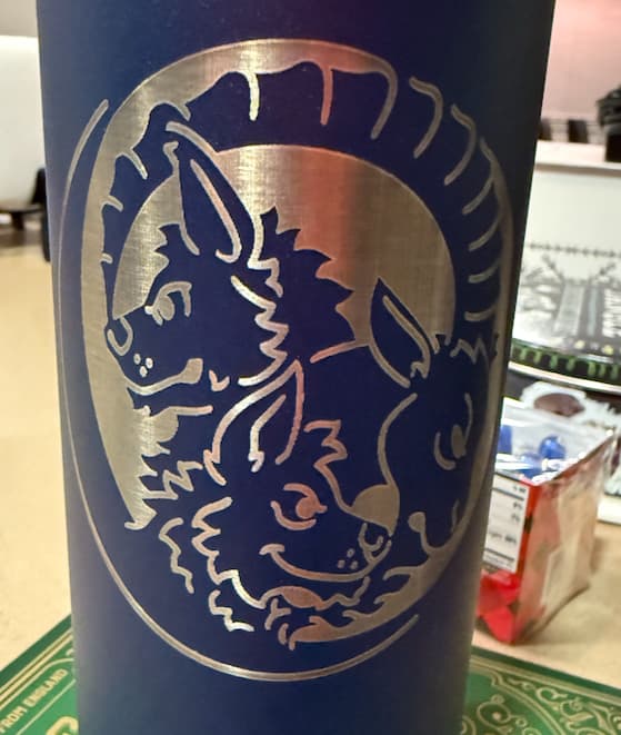
What’s strange is that with the apparent trouble my machine has, it can do things like this just fine:
If your test was done on a roller rotary then that could account for the issues you’re seeing. You typically do not want to be rolling back and forth on the rotary which is what will happen with line mode. If you do use this method, you’d need to make sure you have good grip and not accelerating too quickly. The reason you likely don’t see that in your good example is that it was done with a scanning (left and right) operation with the rotary only turning in one direction.
If you’re trying to fine-tune the machine then I’d suggest starting on something flat. If you’re sufficiently satisfied with that then move to rotary.
Took some advice and ran the test more slowly on a flat surface, not using the rollers, and the output is much better. So I can assume the machine is dialed in - and I would hope so, it’s brand new - and now only have to worry about calibrating the roller for my purposes. Thanks!
We’ve diagnosed problems with machines fresh out of the box with bad components, ranging from misaligned mirrors and defective power supplies in CO₂ lasers to stripped screws and mismatched belts + pulleys in diode machines.
When you’re looking for problems, do not assume the machine arrived in perfect condition!
Just updating folks - I’ve made progress on fixing the issues I’d noticed that prompted me to check the machine’s alignment/settings.
-Printed an alignment test (see download above) on a flat surface without the rotary. Satisfied with results.
-Added the rotary back in, alignment test showed the Y axis off by quite a bit - a 90mm circle printed as a 90x105mm oval.
-Adjusted settings in the rotary wizard, ultimately wound up dialing back the ‘mm per rotation’ to 39.5, the rotary wheel size to 16.3 (accurate for the Creality roller I’m using). This produced a test where the rotary wheel spun exactly 1 rotation, and produces a circle on a cylinder that, when flattened, is 90x90. Perfect.
Thanks for the help and advice to a newbie! I’ll be around!