In this thread, the Lead Dev @LightBurn mentioned that the focus test can be set to a -ve to +ve number, which is logical as you want to test both sides of the 0 focus. However the UI only allows +ve numbers…
I don’t think the intended meaning is that you enter negative values. I think the intention is to cover a negative and positive range of values from the nominal reference height.
So as an example, if your nominal focus height was 5 mm, try testing values from 3 mm to 7 mm.
My default offsets are set to 0. So I’d want to test from focus either side, which would be say -2 to +2.
I can’t see anywhere where my focus is currently a positive value to be able to do what you suggested?
I’m expecting the result to be a value + or - that I can enter into the autofocus g-code… If it’s always a positive number that assume the correction is just one way?
Sounds like you’re conflating 2 things: offset values at the cut layer and how to approach the focus test.
The focus test is intended to help you identify ideal focus distance. Once you have that information you can use that to inform other decisions about how to focus.
Ok suppose for example I have a TS2-20W and I use autofocus to set the focus, but it seems to be slightly off. So I then run the focus test and notice that +2mm seems to be the best value. Where do I enter that +2?
AFAIK there’s two options:
I can enter the +2mm in the offset for layers or edit the GCODE for the autofocus to add an additional +2.
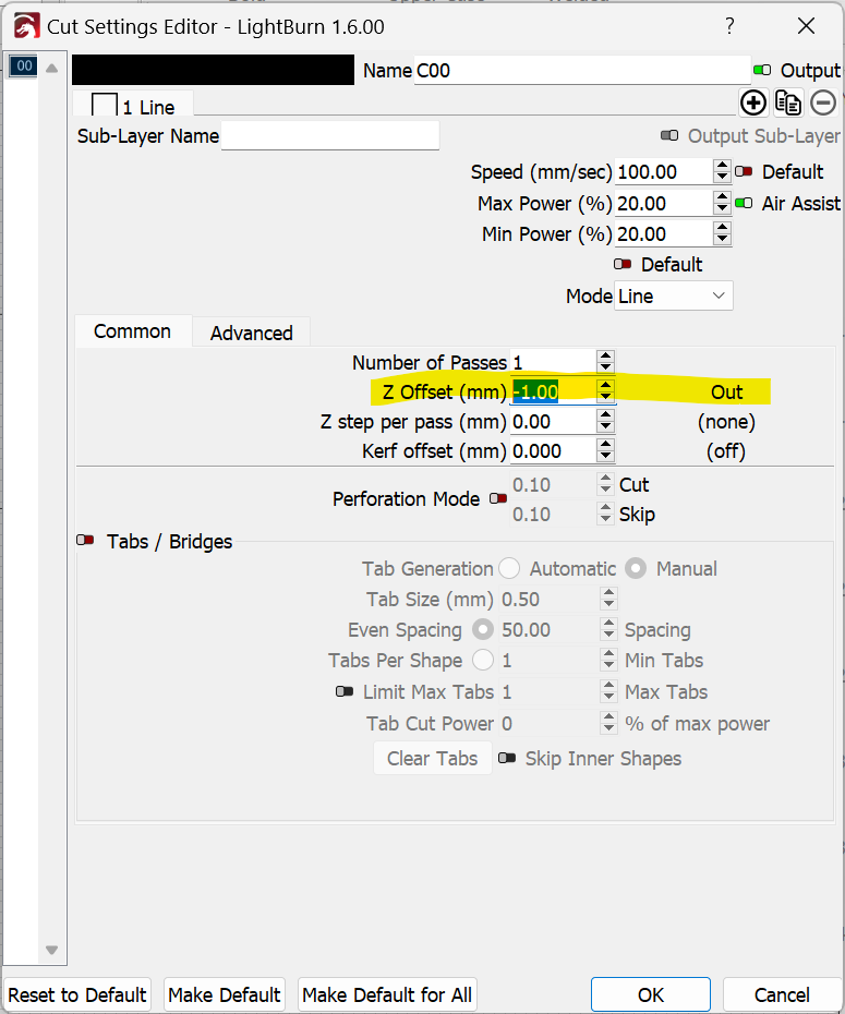
Notice the Out indicator. Going to positive would switch that to In.
Having said that, there may be a way to directly adjust the ideal focus value for your specific machine, either mechnically or through software but I’m not familiar with your specific machine.
Ideally you wouldn’t use the offset to achieve basic ideal focus.
Are you asking in principle how that would work or are you asking mechanically how would this be achieved?
If the former, you’d need to transpose the values so that the lowest focus point starts from zero.
If mechanically this will somewhat depend on your machine but the basic steps:
Set focus on your laser
Measure distance from laser to material
Lower the laser down to what you want your 0 distance to be and note the difference between that and previous measurement
Run focus test
5 Transpose results of test back to previous measured value
Or don’t use the focus test at all. Create lines on separate layers and use offset to apply your positive or negative values. Run the job and determine ideal focus. Once identified, make the physical, configuration setting change, or workflow change to achieve focus.
I went thru this a number of months ago. I ran my autofocus macro, then jogged down 1mm at a time until it touched the material, then jogged up 1mm at a time until it stopped. For me, 40mm total travel and 7.5mm from material to focus probe (8mm to nozzle). To run the focus test within what seemed a reasonable range, I ran the autofocus then jogged up 5mm and ran a test range of 10mm that gave the range from -5, 0(default), and +5. I then used the offset in the layer properties and save per material and process. Offsetting from the default focus position.
After much back and forth with many materials and processes. I ultimately decided my own test, as PY suggests above, was much easier and faster.