Hi
I’m planning on a hudge mod for atomstack x40 pro
I just need a bigger … Much bigger working area and spot on repetitive.
Tried to check the ttl property but only thing I found was pwm value $34-1
Laser mode enable $32-true
And max speed rpm s value min max 0-1000
Didn’t find ttl frequency (laser is connected with 5 wires so I thought 2 for power 3 ttl)
Isn’t there another method than using oscilloscope on ttl to check the impuls value ?
I want to use mks dlc32 v2.1 for a main board so I can attach z axis motor and change open loop to closed ones
There is no standard $34 with these that I am aware of… The pwm relationship defaults to 1000 (S-Value Max). It needs to be equal your $30 parameter.
The pwm period is 1mS or 1kHz base frequency. This is set within the boot SD card, if I remember correctly.
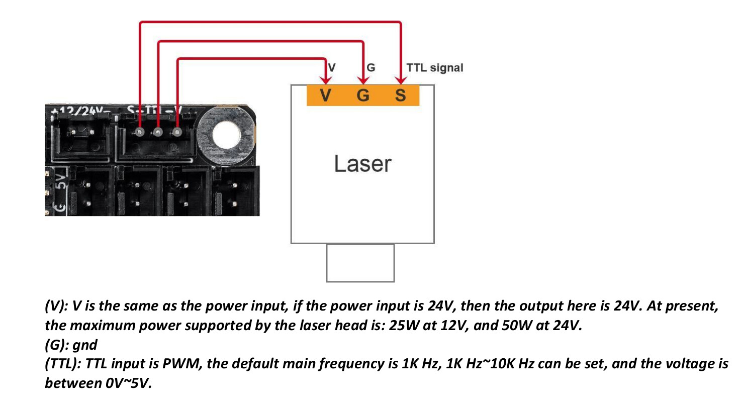
The laser module only needs 3 wires… Ground, power and pwm. My NEJE module has 4 wires, one of them is the temperature sensor. Can’t find that head on your machine with a pin out telling me what is what, so that’s up to you to figure out… If you find it, post it…
Can’t beat a scope, however you can easily check these by measuring the voltage. It will display an rms voltage… on a 5V ttl interface 50% power will read 2.5V, 20% 1V and 100% 5V…
The output pin of the DLC32 for ttl are the top right… S is the output ttl control. Don’t exceed wattage listed for V+
I think that it has 5 wires cause the power needed to run module was way to high for the 3 connector.
Whole machine is 210w and the laser module has a writing about 24v 7.4a so it’s 180watt power consumption by the module alone… I guess
I’m a engineer but the wood technologist not lasermeister
So sorry if I wrote something absurd
It doesn’t make sense to bring a lot of current to it with two wires, and have only one ground for a return…
It’s possible that you have two pair, two grounds and two power lines… I’m just speculating as I don’t have one and have never seen one in real life. It’s always nice to have some documentation on this stuff.
I’m guessing the module or controller isn’t marked in any way?
To wire this up without losing smoke you need to know how it’s wired. I think 50W is maximum for current draw, so you’ll have to get power to module via a direct line…
It has a basic markings
Ttl is marked and power but no specific information online about values and I doubt that will get the info from atomstack since I had quite a beef with them on the start
Basically yes
I will sent a photo tomorrow cause now i will drive quite a lot.
Last thing before tomorrow xD
Do you know if I can plug any closed loop stepper driver into mks ? Or just theirs modules ive seen both statements on net. Oh and if the frequency could be set via software on that board
C: