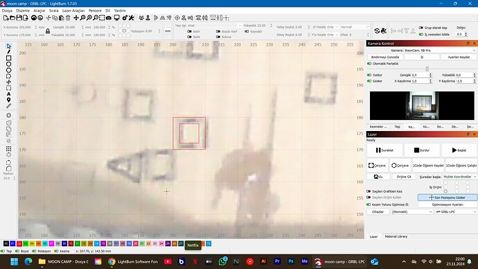
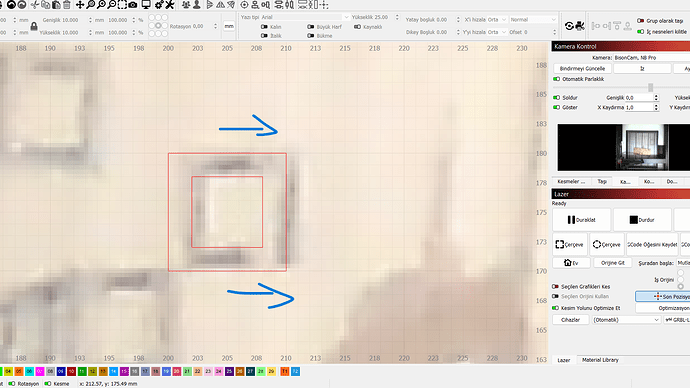
Hello. I calibrated the camera well. As you can see from the screenshot, I filled the frame, but when I took the photo of the work area again, there are differences between where I drew and where the laser drew. How can I fix this?
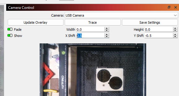
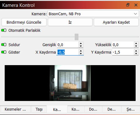
I use Shift Controls under Camera Controls, you must have seen the values there. After drawing the frame, when I update my work area by viewing the overlay, the frame drawn by the laser at the bottom is shifted again. I don’t think the problem is with the shift controls. Is there another setting in the program that I don’t know about? Note: I save the settings after using Shift Controls every time.
The camera system under LightBurn is very sensitive to calibration and bed height (focus camera to surface material). Changing this distance, even just a little bit, will cause this inaccuracy. You will get the same error when the 4 marks are not hit very precisely at the last part of calibration, the image becomes slightly distorted and this can cause this inaccuracy.
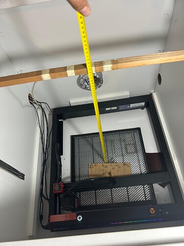
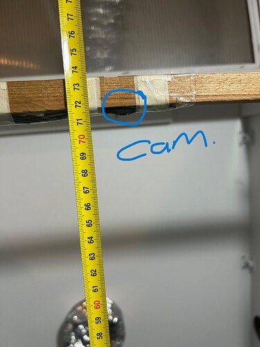
I didn’t buy the camera I used, I took it out of a laptop and it was a laptop camera. The focal length between my work area and the camera is: 71.5 cm
As long as your construction is stable and you remember that the height from the time you calibrated your camera should be the same as when you use it with the material you want to process in the laser, then it should work. This means that you should calibrate with e.g. 3 mm height on your machine bed if you work with 3 mm material afterwards. Remember, a single mm in distance or half a degree change in the angle of your camera, can ruin the result. (This is not theory, this is practical experience from 3 different laser machines)
So, according to what you said, we need to calibrate the thickness for each product. Don’t you think this would be very tiring? I don’t work with only 3mm high material. I can’t work with 5 pieces of 5mm and then 10mm? fixed product. What if we close the program and reopen it for each product?
The only way I know where the material thickness is not a problem is if you have a height-adjustable machine bed. Here you bring the surface/focus of the laser and thus also the camera to the correct height again when changing materials.
Theoretically you can make different calibrations and save them in each camera profile.
But using 5mm material on a 3mm adjusted camera profile does not work.
As you said, can we make the camera settings like this then? For products with different thicknesses, for example: 3mm plywood Shift Controls Y= -1 X= +2 \ For leather with a thickness of 1.2 mm, we make X=2 Y=3 and export the camera settings according to the thickness of the products separately. If we import the camera settings when we will work with leather or plywood again, can this problem be solved?
Shift controls are only intended for fine adjustment, e.g. with a large machine bed there will always be some distortion/fisheye effect in the outer areas. I currently have a deviation in the outer areas that I can eliminate with +/- 0.2 to 0.4 mm.
I would try to make complete profiles for the main material heights you work with and see if that is satisfactory. I don’t know how people with non-height adjustable machine beds otherwise deal with this problem.
I did a video on this, how to fix the issue via calibration, and how to save and export profiles for differnt material thickness.
Brian
yours look to be between 5 and 3mm off. Mine is the same way, I average 3mm. But will try the shift settings listed below. If it works I’ll let you know.
This topic was automatically closed 30 days after the last reply. New replies are no longer allowed.
