Hey guys, I’m trying to make a template for a router with a grid of circles that have to be PERFECTLY square.
I have traced the issue back to my laser. I’ve checked the X axis bar for square and even tried minor adjustments by moving the teeth on the belt one forward or back.
I have determined that the laser frame is slightly out of square.
Am I expecting too much or is there a way to do this?
You can test the deviation by engraving a square as large as possible and afterwards measuring the real measurement.
It is not good that you have a frame that is not 4x90 degree, you can’t force it to fit?
What’s money worth these days if you spend $2k and get a machine that doesn’t cut square.
Not familiar with this machine but if the Y axis has two steppers and two limit switches you can square it up in the homing cycle. If not skipping teeth is too course and bending the frame is a risky idea. I’ll bet the X axis has adjustment screws on the ends.
This need to be machinist level square. I have gotten it close but not close enough for what I’m trying to do. I measure diagonals on a test of 280mmx280mm square. One diagonal is .5mm longer.
I’m about to give up and buy a commercial jig (expensive) but had a thought. This laser is in a non-climate controlled environment. Not super cold here but temps varied today from 44° to 68°F. I’m wondering if that could affect the belts.
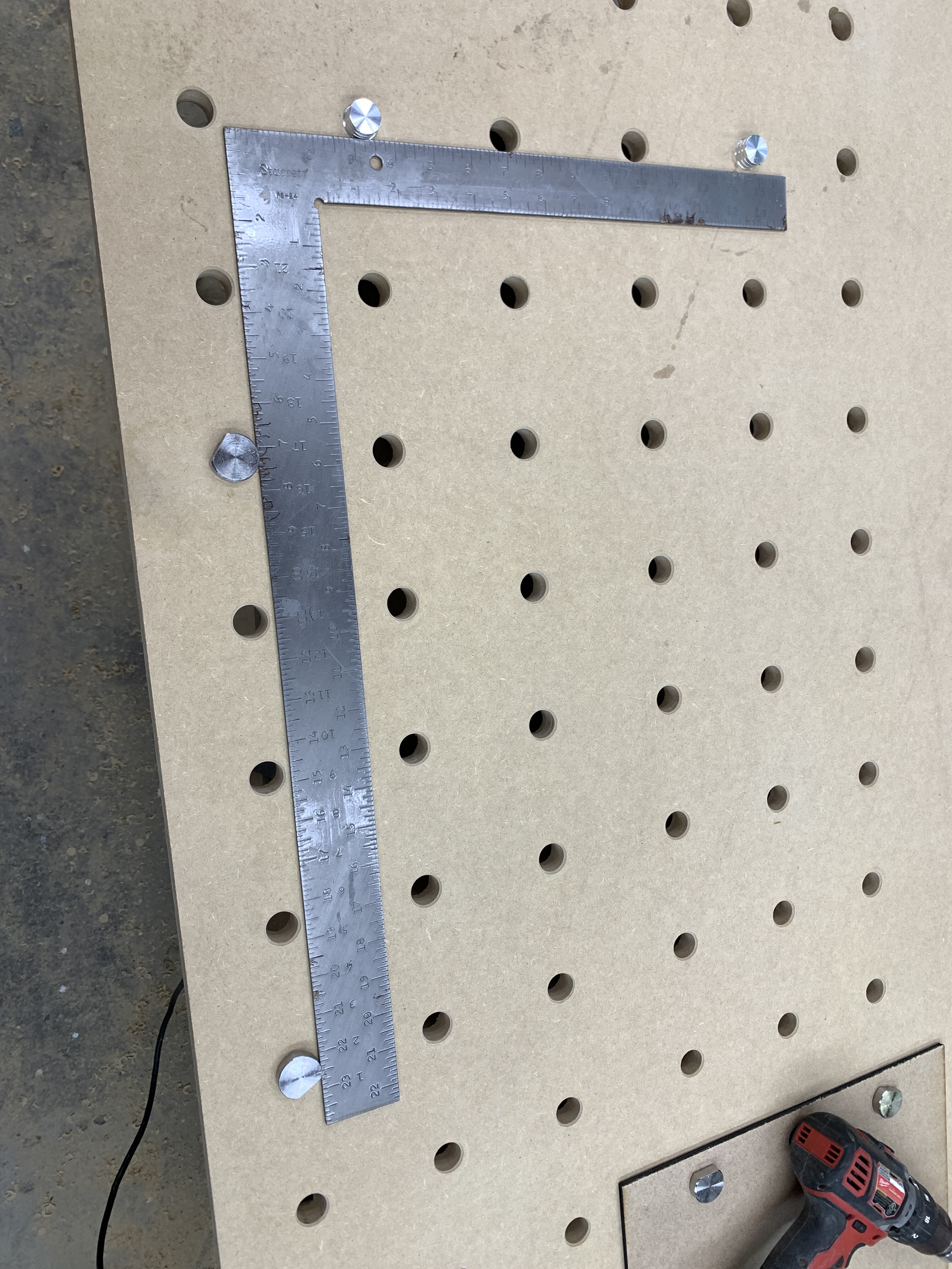
To give you an idea of what I’m doing here is the template. The circles need to be exactly 96mm OC and perfectly perpendicular. The objective is to produce a grid of holes in a workbench top.Look at the short leg of the square to see the massive error that was multiplied across the board.
I suspect this would be correctable but you may be rubbing up against what’s easily achievable. I’d wager that you should be able to get to within about 0.2 mm of square or better at those distances.
First double check that squareness is indeed the issue. Are the vertical and horizontal holes by themselves straight?
This could be an issue with dimension but I’d expect the distortion to be uniform across the machine.
The other thing you’ll need to be able to do is first dial-in the steps/mm calibration of the machine. The stepper motors themselves should be able to get you within about 10-20 microns or so of precision. However, after that gets translated through the belts and everything you should still be in the 100 micron range of precision. So take some effort to dial in the calibration to within 0.1 mm across 100 mm or better.
Note that a variation of 0.5 mm across 280x280 will be about a 0.1 degree deviation at the frame. Get out the machinist square and make absolutely sure that the machine is square at all 4 corners. If you can’t detect the issue there then either there’s something else going on or it will be tremendously harder to get to what you need.
Having said all that, I’m a little surprised by how far off that peg is. That’s only across 2 uses of the jig.
Can I assume you’ve checked your square for squareness and the pegs for roundness?
After checking the gantry I checked the frame. I have to say the frame IS out of square app. 2mm across the width. But the way the frame is constructed there is no way to adjust. I suppose I could try flexing is and locking the legs in.
My square is a Starrett and definitely dead on square.
I saw the stepper settings but have no idea how to work with them. Could you elaborate on that a bit more?
My machine is set up on a base with registration holes for the legs. I was thinking about simply flexing the frame a tad and repositioning the leg holder. What you think?
This sounds like a smoking gun then. Without this being square you’ll never get a square cut. The shape of the frame will be directly imparted into the burn.
The steps/mm is a setting in your controller that’s used to indicate how many microsteps are required to achieve a millimeter.
If this is for the Ortur Laser Master 3 then the default for that machine is 100 steps per mm. This is stored in $100, $101 GRBL config for X and Y respectively. When LightBurn asks the controller to move the machine 1 mm, the controller will request 100 steps from the stepper driver because it believes that’s what it takes to achieve 1 mm.
For various reasons, the actual achieved distance may not actually be 1 mm. Slight variation in gearing, belts, temperature could affect the actual achieved distance.
Out of the factory Ortur machines are tuned fairly well. I’d guess you’d be within .1-.2 mm across 100 mm but you should confirm.
Make the largest rectangle that your machine can reasonably fit. Adjust settings so that it burns the finest line that you can make. Burn the rectangle. Measure the actual vs designed dimensions for width and height. You can then adjust $100 and $101 either manually or by using Edit->Machine Settings->Calibrate Axis in LightBurn to help you with this.
If this is not dialed in, you’ll have no chance of getting to your goal. So both the squareness and calibration will be critical.
My concern there would be uneven flexing along the length. So instead of a leaning rectangle you now have a pillow shape. Are you able to loosen the bolts holding the frame and squaring it up as you retension the bolts? Or possibly shim one side of the frame to retain squareness?
Is your square square good chance it is out of wack take it to a machine shop and have them check it and if it is not right use a punch to pull it in or push it out. Better yet drop the dollars on a good square. Hope this helped