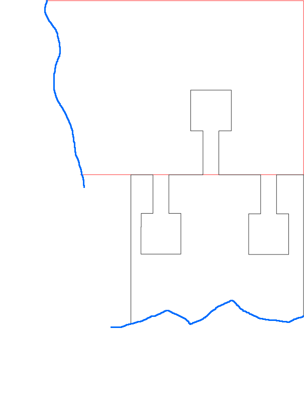
I am trying to add tabs to an existing design. I think I’ve everything in the weld and boolean section without any luck. I’m posting two images.
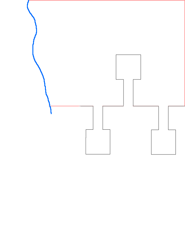
On Image1 the red line is existing and the black line is what I’m trying to add so I just have the two tabs and the groove. Image2 is where I’m trying to get.
John,
I tried with both on the same layer and it didn’t work. I’m including the file. I can’t show the entire file because it is someone else’s file I’m trying to modify with extra tabs.
I Closed each shape, put each on separate layers. Then duplicated them and subtracted from each other. I am probably better at doing it than explaining it . Oh I did have to delete a few hidden double lines. Practice doing it with something more simple and you’ll get it…
I generated a quick drawing and made three dupilcate lines and applied the bridge. the bridge was generated on one of the lines but the gap was obscured by unaffected duplicate.
I’m confused. I overlap the top and bottom pieces so they line up. I subtract the bottom shape from the top and all I have left is the top shape with only the single tang void and neither of the two bottom tangs.
Increase the overlap so the entirety of the part you want the negative version of is represented in the overlap. This is why I mentioned that you may need to increase the area at the bottom of the top piece. This would be to account for the additional required space.
Jim did what I wanted to do but I don’t grasp his explanation. That’s not his fault. I have a very high mechanical aptitude and that gets in the way with things like this. If I could build it with my hands there would be no problem. If I could do it in Illustrator or Photoshop I’d have it done. I just want to learn how to do this in LB so I have the file be the correct size and be where I need it.
I appreciate all the time and help you all are giving today.
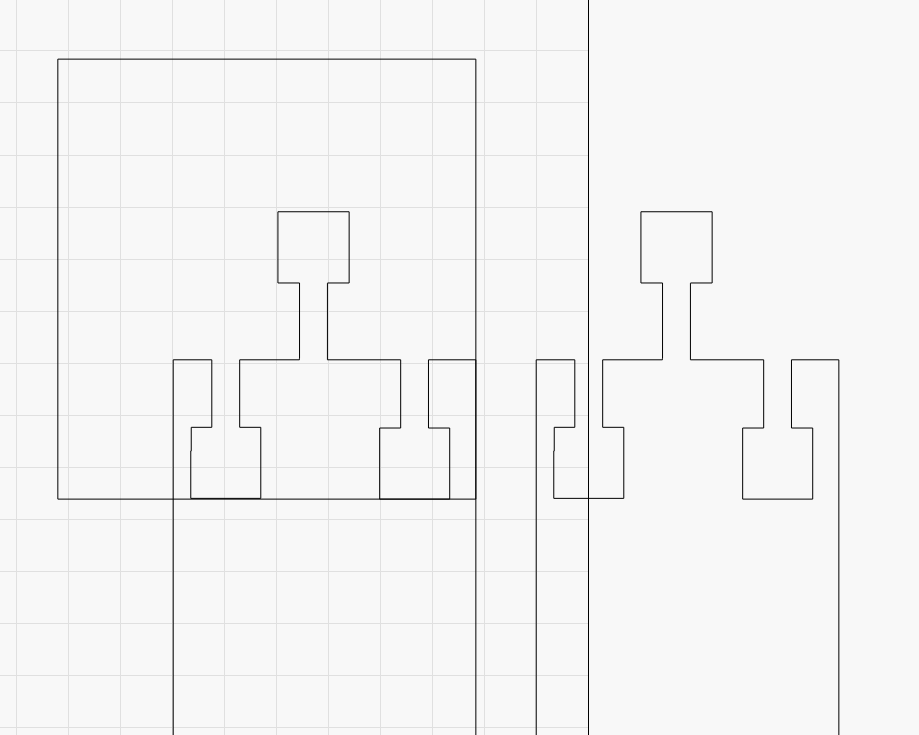
I pulled down the first one and looked for alignment issues.
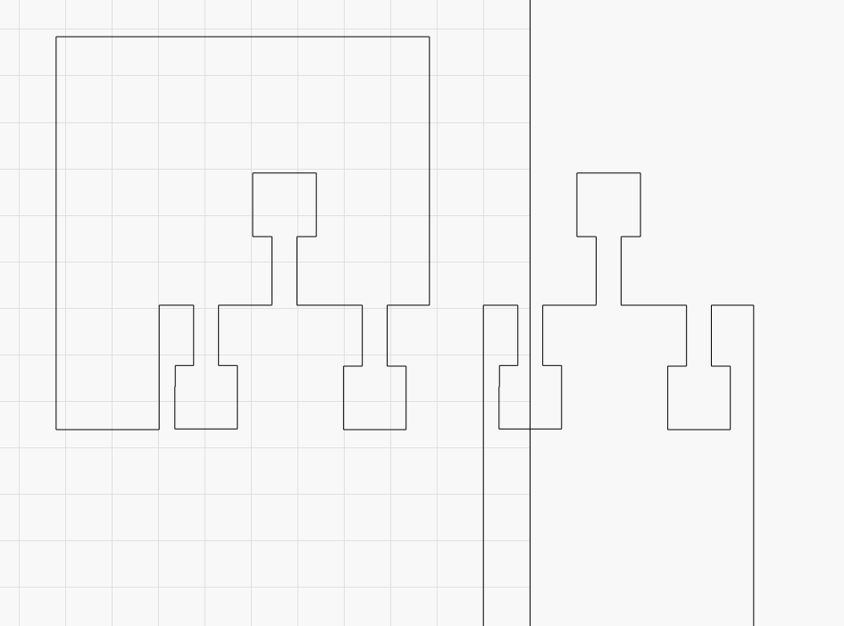
Maybe my tolerance settings are different, but I couldn’t get the Boolean operations to work as desired without leaving anomalies (remnants) from one or the other until I corrected the alignments. See attached.
Wondering how you all got around these issues and got satisfactory results.
I noticed some of the design problems but was answering the technique issue without focusing on any design considerations. @ErnieHodge had already indicated this was a partial extract of the original design to illustrate the complication so any design issues I considered moot.