I have a Mopa Monport laser and I need to locate small engravings very precisely (for watches).
The red laser is too wide to be accurate to +/-0.1mm.
Will a camera give me better results?
If so, which model do you recommend?
For the moment, the best way I’ve found is to make copies of the parts to be engraved in 3D printing, then engrave them, replace them with a new 3d print and repeat until I get a good result.
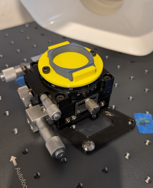
I place the prints on a template screwed onto a micrometric table.
But this method takes a long time…
A camera can certainly work on a galvo, but you’ll need to be extremely mindful of focus. If you calibrate the camera to the bottom surface of your galvo, then raise the head up to the focus plane of the watch, the watch should be bang on. Using a linear stage like you have there and fine tuning on a blank is 100% what I would do though, it’s a more reliable method that camera because its the exact thing, vs. a calibrated camera projection.
I don’t know enough about MOPA lasers or the one You have, and how the positioning laser is constructed in them to give You an definitive answer, but my short engineering based answer would be no, it’s not possible.
Not feasibly anyway.
That said/guessed, Your jig will most likely outperform any reasonably priced pointer system by a large margin anyway.
I do wholeheartedly agree with @Colin as well, a jig pretty much like that would (and will) most likely be the method of choice for my application as well (eyepiece graticules).
The reason being the way the laser pointer modules are designed and constructed, and on the other hand the lack of demand for the manufacturers to improve the dot (or line) size.
My lasering is -and has been- on hold for a while for various reasons, but I do intend to upgrade the next to useless red dot positioning laser on my xTool D1 (a basic combined beam 20W and a single 2W IR diode laser) when I get back into it.
My plan involves retrofitting separate X & Y line lasers (or other light sources) to intersect on the focal point of the actual laser.
AND
It’ll involve manipulating the line laser beam with lenses/grates to produce a finer line as well.
And that’ll be the hard -or even impossible DIY way- part of that plan of mine.
You might want to try a head-mounted camera system. I played around with it a while ago but clearly remember that the visible area itself was small but the precision was excellent.
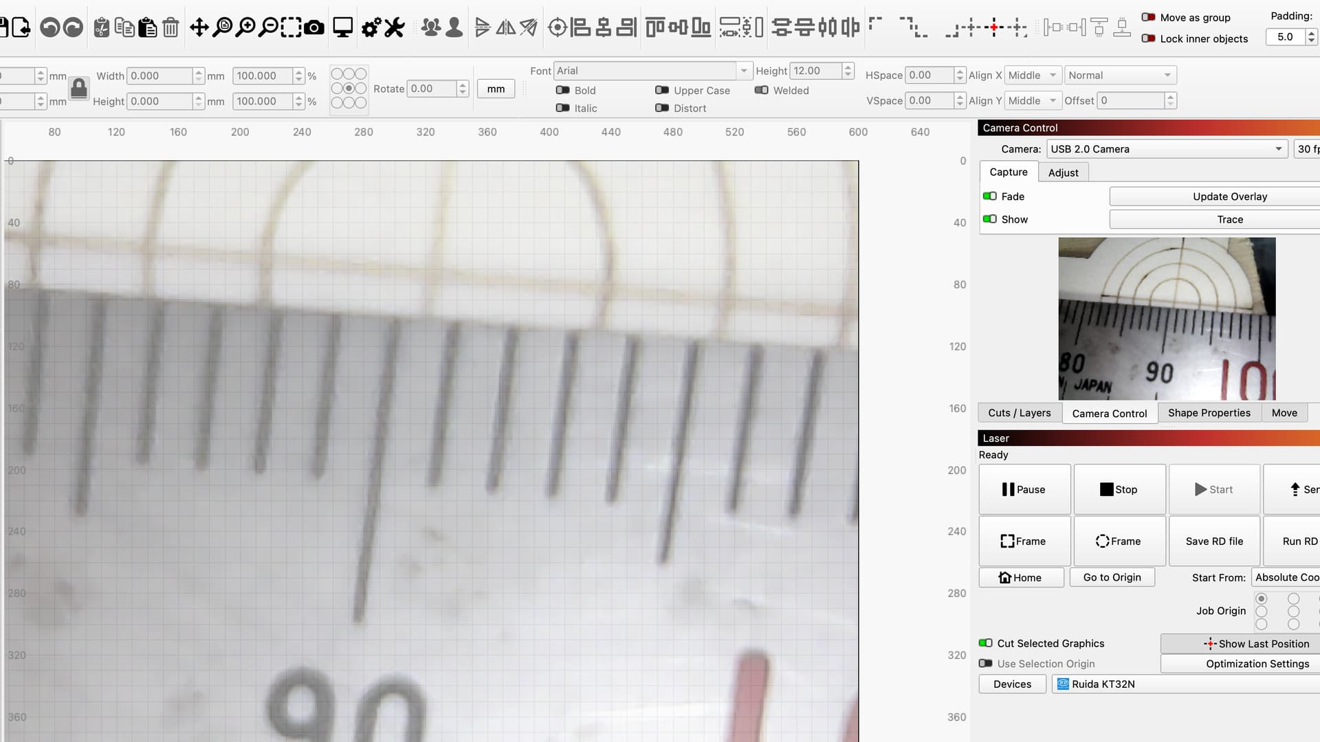
I used a very cheap inspection camera at the time, with built-in light. If you can find a way to mount such a camera on your laser head itself, without it getting in the way of the laser, the visible area will be approx. 200x200 mm at approx. 200mm distance, that’s what I measured this time. On my CO2 laser the camera was mounted approx. 25mm distance from the surface and the field of view is very small, see picture.
For my work, however, the head-mounted camera was not very useful and I switched back to a “normal” camera system and use it daily, but for your precision work it may be an option.
Maybe off base here, but I’ve tried to keep alignment between machines. It’s nice to make a pcb, but they generally require holes for mounting or thru hole components. So to drill them I need to move them to another machine.
The only way I’ve found to register with the fiber, is use the center for a reference. In general it works well enough to make centered coins. I use the P center the graphics.
I also enable Edit → Settings → Display → Show work area center cross.
Your jig is very nice, but seems to me it might be quicker to line it up once in the center. At least it’s repeatable. You’ll have to let us know.
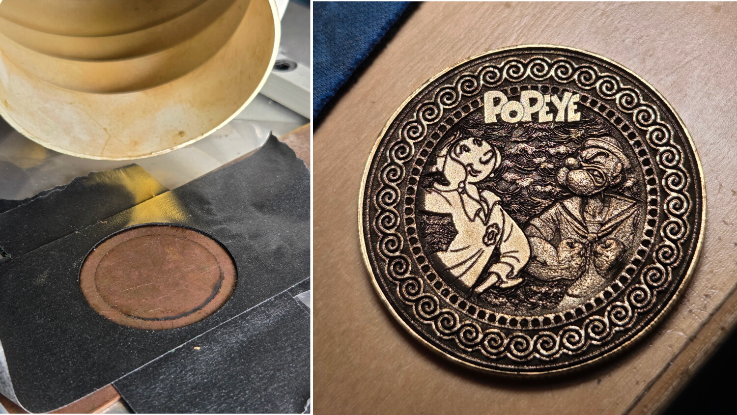
I commonly lay down a piece of steel, then layer a few pieces of tape to it. Use the fiber laser to cut the outline of the coin out then remove it. This leaves a pretty good indentation to snap the coin in place… Some coins have rounded edges, not square edges, so I put a few more layers of tape to ensure enough of a lip to position the coin.
This jig, and the coin… although it’s not cleaned up, it look pretty well centered.