Bonjour, je viens d’acheter une Mecpow G5 et je n’arrive pas à la faire fonctionner.
J’utilise une graveuse Comgrow Z1 avec le câble noir de la rotative et le logiciel Lightburn version 1.4.
La rotative se met à tourner et s’arrête aussitôt, le laser fait son cycle normalement.
Les deux moteur de l’axe Y sont débranchés, j’ai branché le câble noir de la Mecpow sur la connectique du moteur gauche.
L’ordre des fils sur la connectique Mecpow :
Orange
Vide
Vert
Rouge
Vide
Bleu
J’ai vérifié les continuités des 2 moteurs et j’ai les valeurs suivantes :
Bobine 1 : Bleu ↔ Rouge = 5 Ω
Bobine 2 : Orange ↔ Vert = 5 Ω
Toutes les autres combinaisons donnent infini.
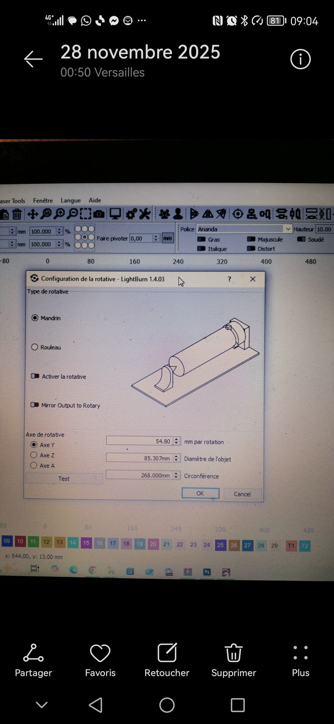
Sur lightburn, j’ai sélectionné “mandrin”, “active”, “360 mm/tour”, “80 de diamètre”.
Pouvez-vous me dire d’où pourrait venir le problème ?
I don’t know the machine in detail (Comgrow Z1), but if I understand correctly, you connected the rotary engine motor cable to one of the Y-axis connectors.
If the machine has two Y-axis motors, it probably also has two connectors (one for each motor), and most likely it will only have one drive to control both motors.
My question is whether the power of the two motors is equivalent to the power of the rotary motor and whether the drive configuration will need to be adjusted.
To avoid all this confusion and complexity, I would opt to use another axis, but I don’t know if the board that comes equipped with the machine allows it.
Someone with more knowledge on the subject could give better help.
Trying to provide a solution without seeing the problem at hand is a shot in the dark. However, just recently someone complained about an identical problem, and it was due to excessive speed.
If possible, posting an image of the problem and a screenshot of the recording settings always helps to understand the cause of the problem.
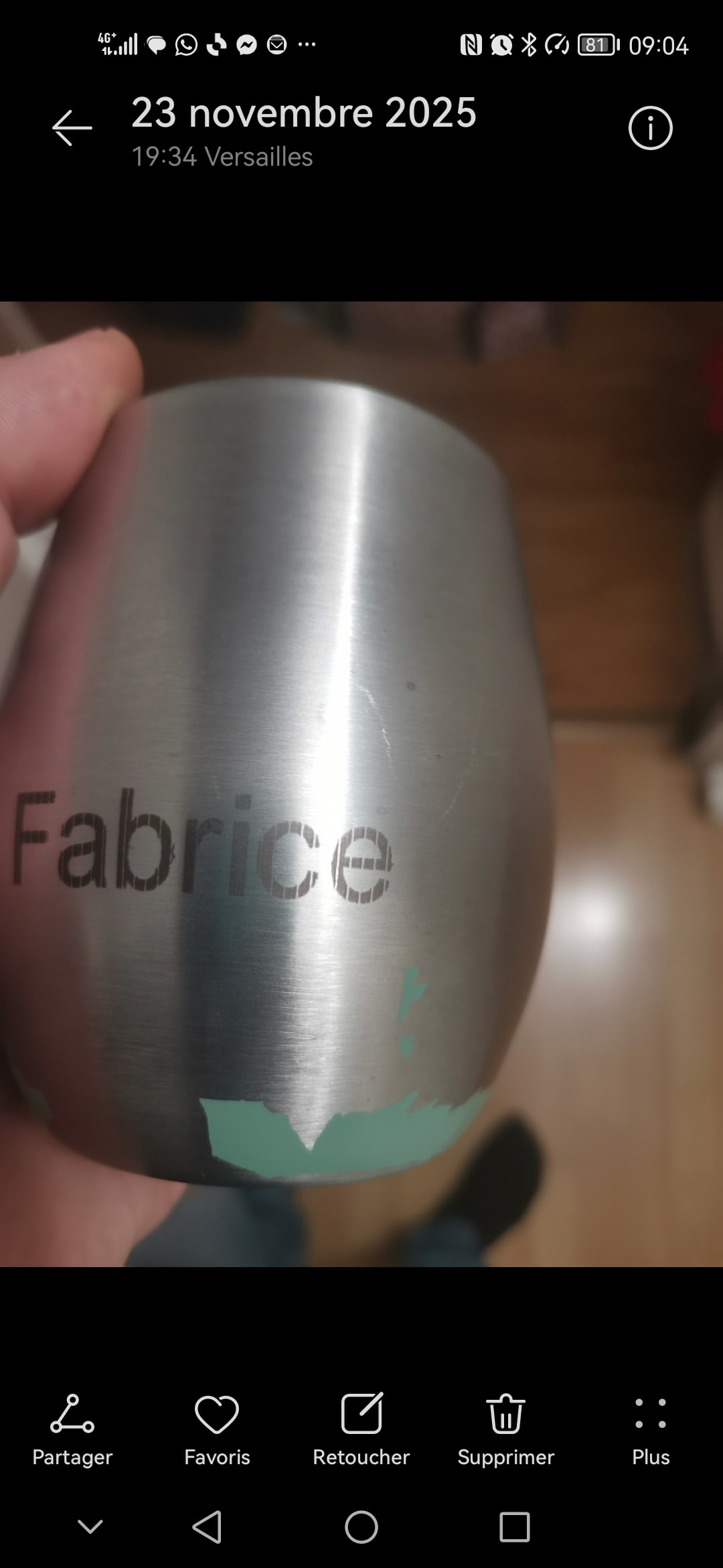
Je te mets mes réglages et ce que donne la gravure, la gravure est hachuré régulièrement.
Les paramètres de la rotative sont bons je pense. Quand je lance le test le verre fait bien 360 degrés, si je diminue les mm par rotation je ne fais plus le tour complet.
I have no experience with the rotary system. I only understand the concept, and it is based on that that I try to help.
If I understand correctly, the number of rotations per mm will have to be a fixed value for the part you are working on and only changed when you change the diameter of the part you are working on.
The settings to be changed after that step will all be in the “cuts/layers” window.
But it would be good to hear the opinion of someone who works with the system because I feel a bit in the dark…
Sorry for the limited help, but I’m in a bit of a hurry today.
C’est tout à fait ça, j’ai essayé tout ce week end même en changeant des paramètres rien ne change. j’ai toujours cet intervalle régulier sans gravure.
On dirai que la rotative tourne un peu plus vite par moment.
If you haven’t already consulted those documents, please do so.
Meanwhile, I noticed you have the line spacing set to “0.08”. I don’t think that’s excessive, but try changing it to 0.1, test it, and see if there’s any difference.
Unless you made a mistake when writing the value, 0.01 is excessive.
0.1 is acceptable for most diode laser machines.
As an experiment, and just to check if the controller board is receiving the information, I set the line spacing to 0.25. This should result in a engraving where the lines are perfectly perceptible. The fault should not manifest itself.
Do the tests on material that you can discard.
Instead of engraving on the rotary surface, if you engrave on a flat surface, does the error repeat?
How does the image appear in the print preview?
Can you post screenshots and images of the results?
Diagnosing a problem effectively from a distance is never easy.
Quand je grave à plat pas de difficulté, l’aperçu quand je grave à une vitesse de 500 MM et 0.08 d’intervalle sur cylindre ou sur plat est le même et j’ai des traits sur le cylindre mais pas sur le plat.
J’ai essayé l’intervalle à 0,01 (c’est possible), c’est très long mais je voulais savoir si le fait de repasser sur les traits permettait d’éliminer l’ecart, j’ai essayé également à 0,25 comme tu m’as conseillé, j’ai toujours les mêmes traits.
The mm per rotation settings depend on the motor and stepper driver combination, and the firmware settings for steps per mm.
LightBurn uses this value to tell the rotary to rotate 360 degrees.
We don’t know yet how far this one rotation moves the surface with one rotation.
The actual distance (size of the slices) is defined with the Object Diameter (or circumference).
Let me explain: If the rotary is not enabled, LightBurn thinks it’s controlling the Y axis of the laser, even when you attached the rotary to the Y-Axis motor.
Don’t “dare” apologize if it’s to correct what’s wrong. I’m the one who should be thanking you, very much!
I thought that mm per rotation was directly related to the perimeter.
Since it isn’t, your explanation didn’t clarify things for me and left me somewhat confused.
But I don’t think you explained or expressed it poorly. It’s just that I’m not “seeing the whole picture”.
Can I assume that the mm per rotation parameter is equivalent to the “Max travel” parameter of the X and Y axes?
I should be sleeping here…
Obviously, the area of a circle changes according to its diameter.
@tex78000
That’s why I’ve mentioned several times that I lack experience. Unintentionally, I end up making mistakes that lead you astray. Sorry for that.
Machines by themselves don’t know what a millimeter is in the first place.
There are GRBL firmware values that tell the controller how many steps the stepper motor needs to perform to move a linear axis one mm.
Now, if we are using a rotating axis, we still command the axis to move in millimeters, and the firmware converts this to the number of steps.
At the risk of overcomplicating it: When using a rotary on a galvo, this part is easier to understand, because LightBurn directly works with “Steps per Rotation”
The “Max Travel” you mentioned is also important when using a rotary:
It tells the machine how long the linear axes physically are. (It’s controlled by the GRBL settings $130, $131, and $132)
You can think of the rotary as a linear axis wrapped around the object.
Now, the rotary can hold an object with a circumference that’s longer than the maximum travel of the Y- or X- axis it’s replacing.
Whenever you (or LightBurn) command the machine to move past the physical limits, the machine throws the Alarm:2 (If Soft Limits are activated.)