So here I am again.
Cables are switched and y axis needed to be inverted.
So did homing direction for X and Y.
Settings for X and Y were the same except for axis length, which I did correct.
Apparently everything is working just fine with setting origin to the top right.
There are some negative coordinates after homing:
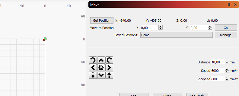
Does that mean I have to do the workspace offset thingy?
Also the limit switches and homing are a little odd to me.
My board has 3 pins for each limit switch (Sig; 5V; GND). I somewhere read to use Active-High configuration so I wired them up like:
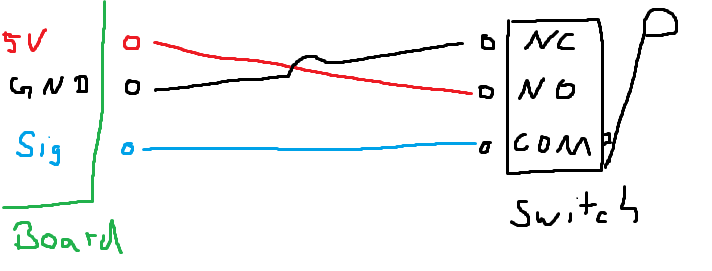
Which did work with $21 and triggered an alarm when bumped.
Homing did not due to “ALARM:8
Homing fail. Cycle failed to clear limit switch when pulling off. Try increasing pull-off setting or check wiring.”
Setting $5=1 did work but the description of $5 says “NOTE: If you invert your limit pins, you will need an external pull-down resistor wired in to all of the limit pins to prevent overloading the pins with current and frying them.”
And since I don’t have a pulldown or any suitable knowledge in electronics I might just ask again what to do?
If I set $5 back to 0 it does still work, when wiring like Active-Low as the description of $5 requests:
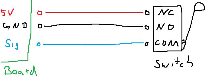
But which is this correct and safe way to go without any pulldowns?