Installing limit switch Alarm 8

Hello,
I am installing my limit switches for the Sculfun S9.
I followed the installation video on youtube step by step. Unfortunately I am not able to install a correct homing position.

These are my machine settings:
$0=10

$1=25

$2=0

$3=0

$4=0

$5=1

$6=0

$10=1

$11=0.010

$12=0.002

$13=0

$20=0

$21=1

$22=1

$23=2

$24=200.000

$25=3000.000

$26=244

$27=6.000

$30=1000

$31=0

$32=1

$100=80.000

$101=80.000

$102=250.000

$110=6000.000

$111=6000.000

$112=1000.000

$120=1000.000

$121=1000.000

$122=1000.000

$130=395.000

$131=395.000

$132=200.000

I keep receiving [ALARM:8 Homing fail. Cycle failed to clear limit switch when pulling off. Try increasing pull-off setting or check wiring] when I use the reset button on the “move tab”.
Also the laser does not move at all.

I like to know how to fix this.
Thank you in advance for the effort.

Try setting $5=0.

Hopefully, you didn’t flash the firmware as the video suggests. You shouldn’t do that, this causes many issues.

Test the switch is working correctly by pushing it with your finger first. Does the machine stop and then try to seek again? Yes? then the limits work.

Home the machine again.
If then you get the pull off error then increase your pull off distance. ($27=XX)

I’m also getting Alarm8 on my Snapmaker Ray, 20w.

Does your machine do this:-
Moves toward Home - Stops in corner - Steps out X 2mm Y 2mm (set by $27=2 also tried 3,4,5 & 10mm) The module does not sit back into the X0-Y0 - Issues Alarm8 and usual msg.

The machine is new and I have put the issue to support…waiting to hear back.

Misken’s comment on $5 was interesting so I did a search…See below.
Also interesting is the bit about Noise.

GRBL Setting $5

In GRBL, setting $5 to 1 inverts the limit pins, meaning the pins are interpreted as triggered when they are high instead of low. This is useful if your limit switches are normally open (NO) and you want to invert their state. By default, the limit pins are held normally-high with the Arduino’s internal pull-up resistor, so setting $5=1 changes this behavior5 [7].

For example, if you have normally open limit switches and you set $5=1, GRBL will interpret the limit switches as triggered when they are not pressed (open circuit). If you set $5=0, GRBL will interpret the limit switches as triggered when they are pressed (closed circuit).5

It’s important to note that if you invert your limit pins, you will need an external pull-down resistor wired into all of the limit pins to prevent overloading the pins with current and potentially damaging them[7].

If you encounter issues with limit switches triggering immediately, it might be due to noise or incorrect wiring. Checking the wiring and ensuring that the switches are correctly configured can help resolve these issues.25

If you set $5 to 1 and still experience issues, it could be due to interference or noise in the system, which might require additional shielding or isolation of the limit switches.2

Setting $5 to 0 makes GRBL think the switches are triggered when you run a homing cycle, which can cause the machine to stop and produce an alarm if the switches are not properly configured.5

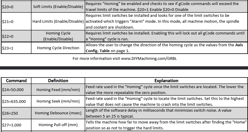
For troubleshooting, it’s recommended to check the debounce timing ($and ensure that the homing feed rate ($24) and homing seek rate ($25) are high enough to prevent the steppers from stalling.

I also followed a CNC thread about Alarm8, Homming alarms with Grbl and as above…Noise/EMI seem to be regular culprits along with connections and cables and propper Earthing.

Hello Melvin
Does $5=0 turn a Normally open into a Normally closed.

Normally Open, mechanical = The switch is wired normally open. It closes when actuated. This is most common for limit switches.**
Normally Closed, mechanical = The switch is wired normally closed It opens when actuated

By design, a switch can be held open or closed and would have opposite wiring.

The $5 parameter says the controller pin is wired for pull-up to +5v or pull-down to 0v signal logic. If the controller board is designed that way, the action of the switch input will be seen as opposite. Just changing the $5 parameter will not convert the switch wiring.

**This is most common because mechanical switch contacts statistically tend to fail (stick) in the closed position due to arcing. For safety reasons, if a switch fails closed, a Home cycle will immediately fail rather than crashing into the frame.

That was the long answer. Short answer is NO.

2 Likes

Hello all,
Thank you for the replies. I tried a bunch of things and finally I managed to make the switches work.
Thanks!

1 Like

What was the fix ?

Changing the $5 changed a lot. Then it was homing just fine without grinding. But the position was y-390 x-390. Via another youtube video I found out a specific code/command to fix thar part. Now it is working as it should be.

My next problem is that when I plugged in my cam500 the entire windows shut down. The error which was shown is possibly trigged due to bad hardware(according to several windows forums), since it happened right after I plugged in the cam500 I assume this is the bad hardware.

So I am now finding out if I can prevent the error in some way so I can use the cam500 or that I need to get rid of that hardware and try another one.

I have not opened a new topic about this on here since it does not concern Lightburn.