Hello everyone!
My goal with this topic is to learn a simple way to connect multiple points.
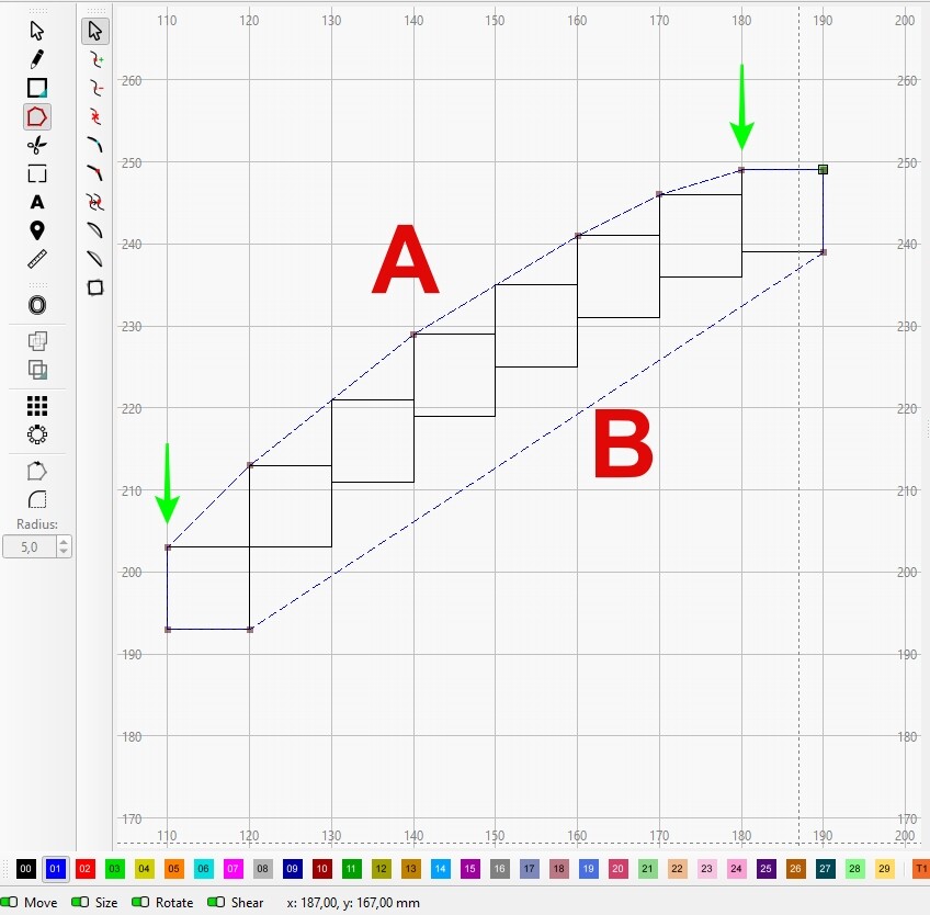
To illustrate what I’m trying to achieve, I drew this to try to explain.
After drawing the squares (imagine as an object), I created a rubber band that resulted in the line shown in blue.
Editing the nodes, I did the following:
I broke the line at the green arrows to create line “A” and line “B.”
If I delete line “B” and place line “A” at the points where line “B” touches, I get what I want to know. (can you imagine line “A” touching all the points of the object?)
This is possible because the top and bottom faces of the object I created are symmetrical.
If the faces aren’t symmetrical, how can I get the final line “A”?
Any ideas? I’m open to suggestions!
I think the easiest way would be to make a line connecting the endpoints and add nodes. The nodes can then be easily and smoothly dragged to the desired points.
Thank’s for your reply Bernd!
I think that will be the way. But,… is always a “but”… this is a small picture example.
I’m thinking in something bigger where this way will be a time consuming job.
I’ve already spent some time trying to achieve a simple way but nothing comes to my mind until now.
Let’s see if more ideas, sometimes out of the box, will enlight this “challenge”.
With complex shapes it could be a problem. On the other hand, I traced and “repaired” an entire font (for private use) and didn’t spend an unreasonable amount of time on it.
Did a quick check and found NURBS Demo (https://nurbscalculator.in/) online. It can do B-Splines, which is pretty much what you are doing with Nodes in Lightburn.
If you are looking for something that will connect the corners with a smooth curved line, I doubt you will have much luck for less than a really lot of money. That is a very specific application for a very complex math operation.
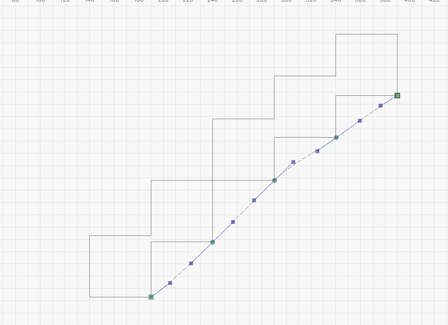
The Pencil tool in the toolbar..under sele tion arrow.
I just now, drew a rough polygon type shape but did not close the shape, and then switched to selection arrow…which brought up the green square, I dragged it to the grey square (finishing point of shape) and gave it its own layer.
I tried it a while back when I didnt know how to insert a node on a line that didnt exist yet.
I think the geometric definition of a “point” needs to be stated…
A point in geometry is a location . It has no size i.e. no width, no length and no depth. A point is shown by a dot.
Even closed, this would not meet any of the requirements. CAD systems for the most part can do a Point. The one I used a lot was EZ-MILL where you could place some Points, then connect them with Lines. A Point was also a Node which could be deleted without affecting the Line.
In your case, you could have just drawn a filled Circle and labeled it as having a 0.01mm dimension. You would have a Dot, but not a Point (and therefore just a single Node).
You are correct, this would have been a Point if you could have done this.
Maybe the problem is me, but your suggestion (NURBS/B-Spline) seems too sophisticated and complex for what I want. Or maybe it’s just my limited brain that doesn’t grasp the complexity of what I am asking for.
The ideal, in my mind, would be to apply vacuum to the line and have it touch the corners.
But it’s still an interesting tool once you know how to use it!!!
I’ll probably try @Pete.IRL approach, which involves connecting the corners with the pencil tool and then, after the line is created, perhaps some processing with “Nodes.”