I know in some cases it is much more efficient to own a cnc router to engrave/cut large areas. But in order to conserve space and money, I already have a 60-watt laser engraver, which I find at times is very inefficient.
So I am wondering is there any data available out there that I could review to determine the cost vs time to pay-off investment for a higher powered co2 engraver?
What are your needs? I chose the physically largest machine possible that could fit through my workshop door. Wattage was/is not the most important thing to me. However, I knew in advance what to expect from my 60 Watt tube.
Engraving times do not change much with larger tubes but the finesse does, the laser beam gets bigger with more power…
If time is important to you and you want to primarily cut, then change your tube and power supply to 80 or 100 Watt. with my 60 Watt I cut (in a reasonable time) up to 8mm laser-suitable plywood (aeroplan BB), up to 6mm MDF/HDF, up to 12mm solid wood, Poplar - I think up to 15-17mm and Acrylic up to 8mm with fine results, but a bit slow…
engraving speeds with me depend on the size of the workpiece, but about 250-300 mm/s
If you have high demands for speed you should also look at other machines, but they are easily twice as expensive as our OMT
Increasing power generally produces a larger focused spot size, which means a wider kerf and lower resolution.
CO₂ tubes generally do not lase at less than 10% to 15% of maximum current, so larger tubes cannot be throttled down to produce the same results as smaller tubes.
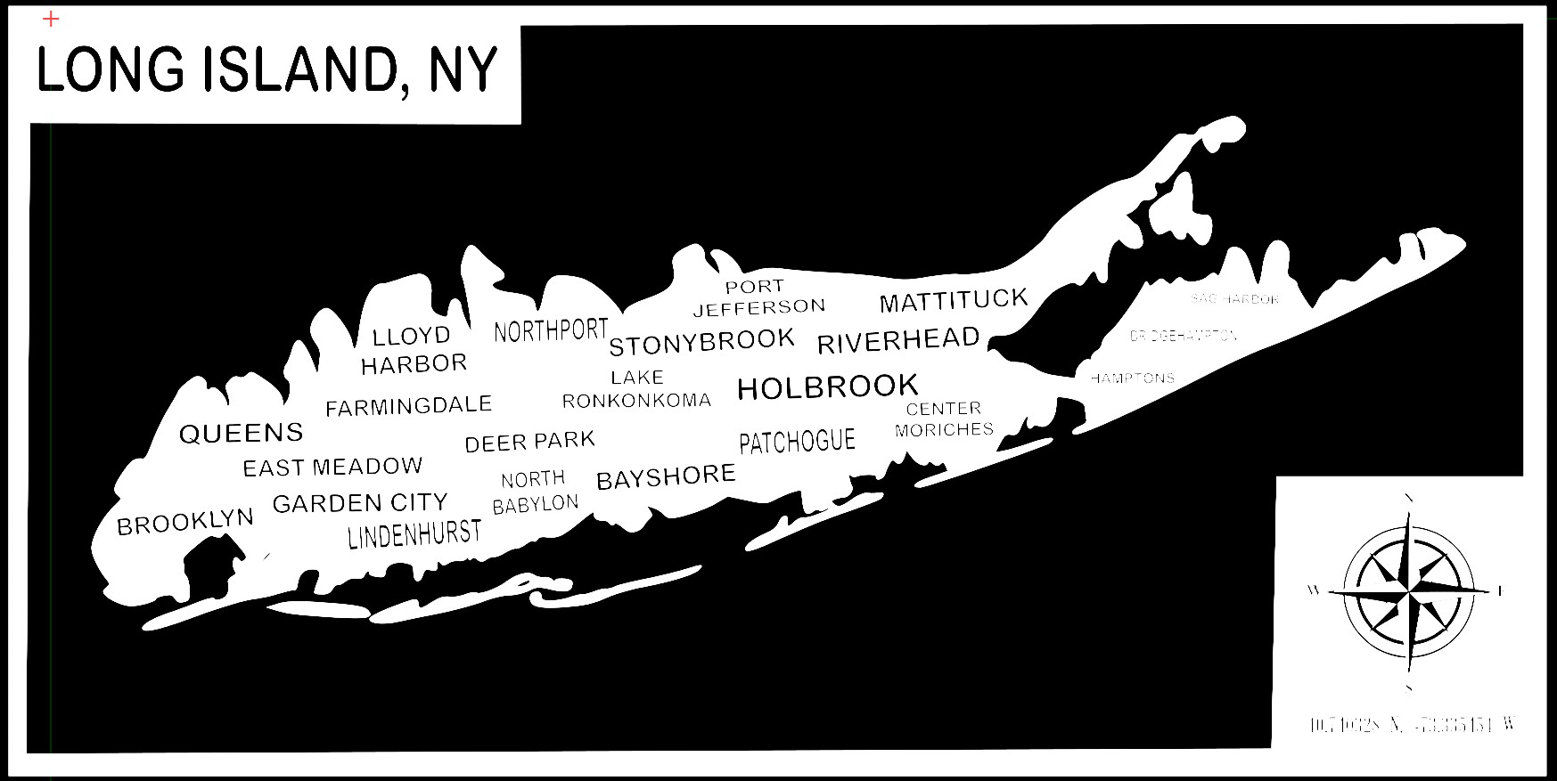
Digging the smallest text out of Long Island will require more care and perhaps different engraving settings than blowing away the Sound, so making two passes with a larger tube may turn out to be slower than a single pass with a smaller tube.
Getting hard data on any of that will be difficult …
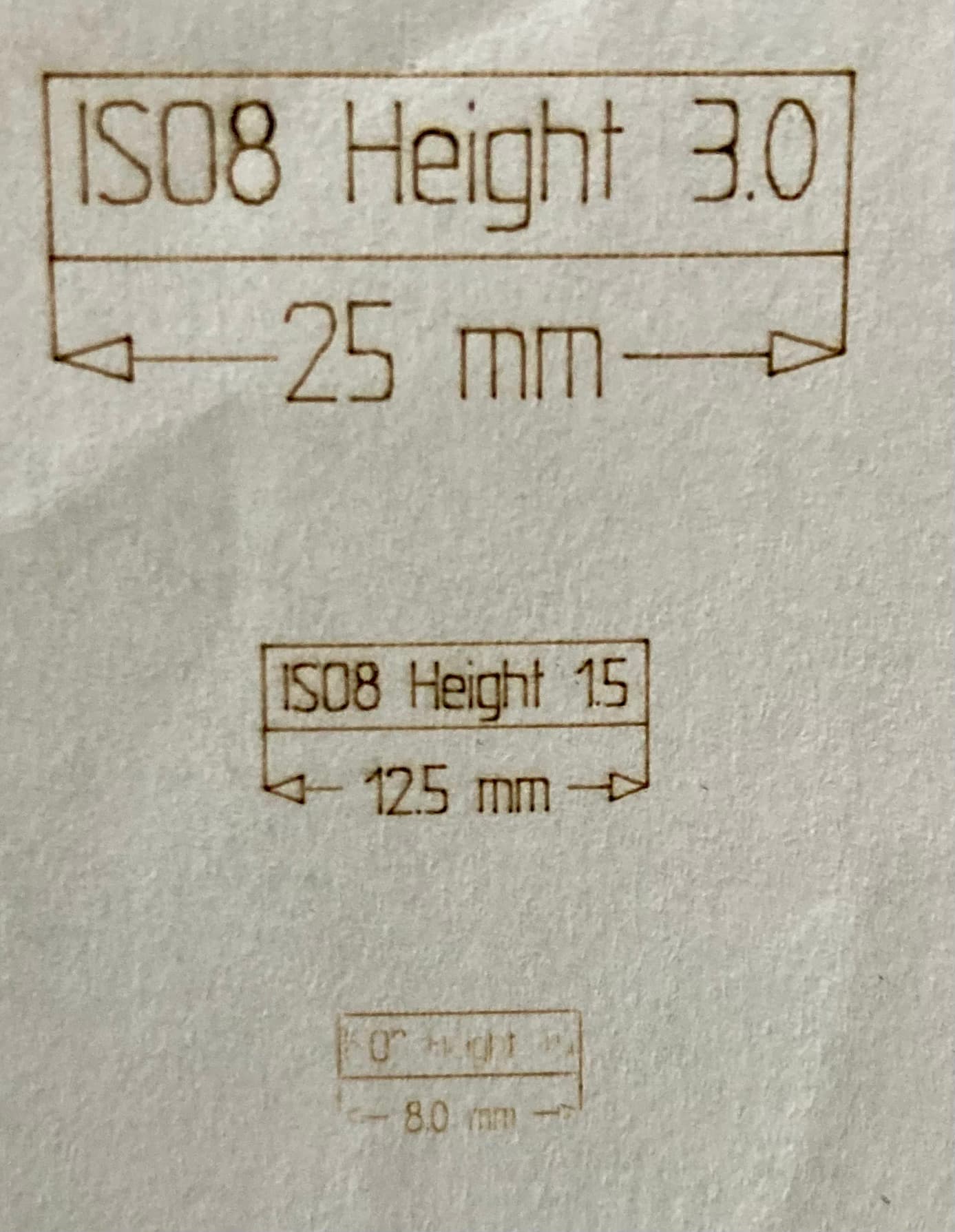
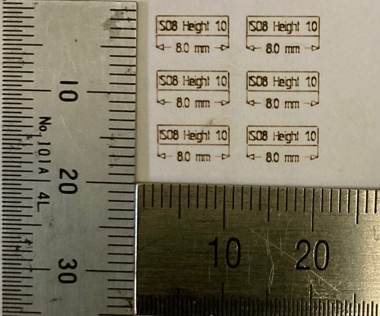
A small example of what is possible (with my 60W CO2).
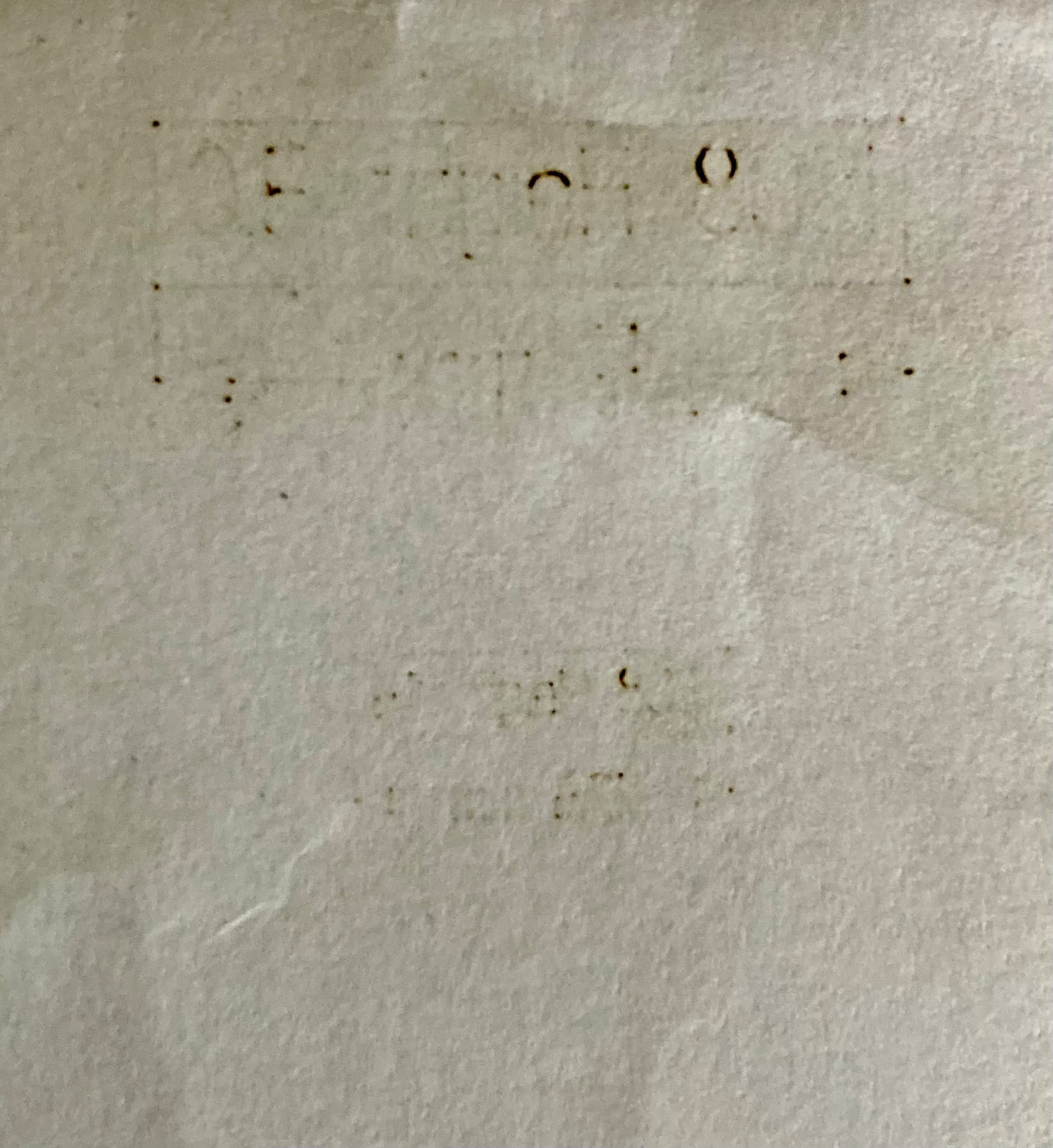
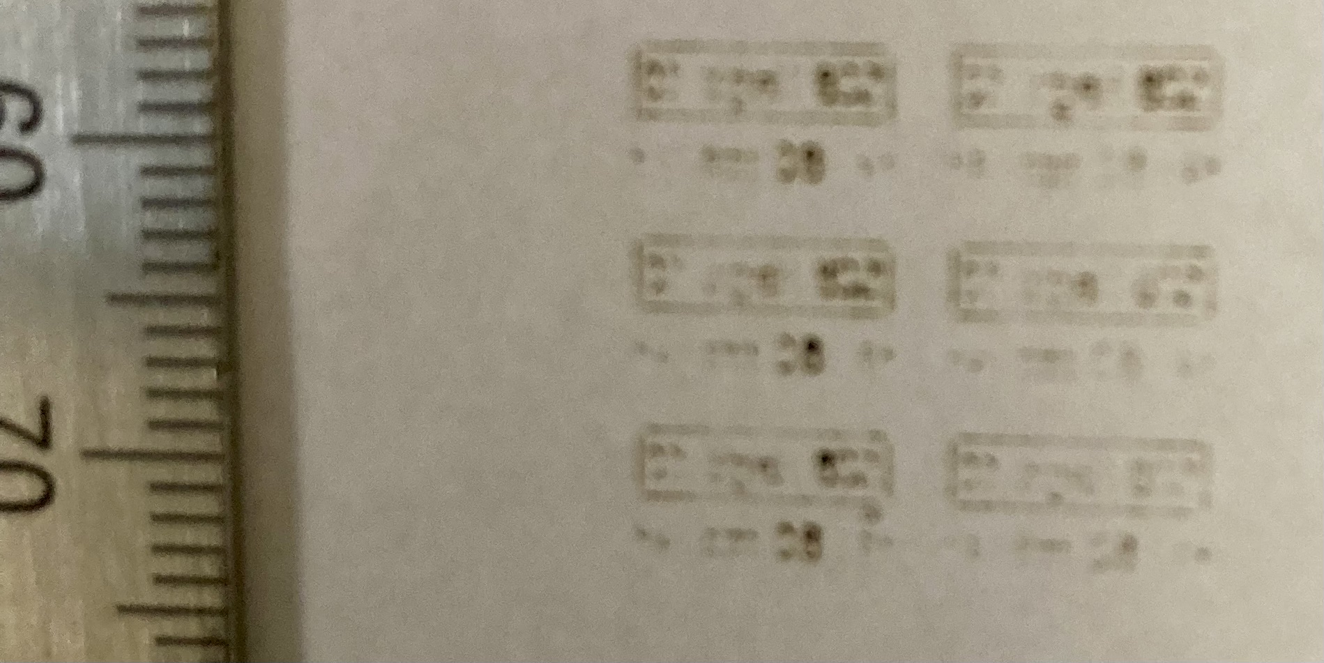
The pictures above are the back of the paper (usually letter paper), which shows the penetration of the laser, power and focus could be worked on a little more. But on most other materials I can engrave, down to 1mm so it is still readable.
PS. My machine can “turn on” all the way down to 8.58%, don’t ask me why.
Actually, you can get larger HVDC tubes to fire at notably lower power just by reducing the PWM frequency. The tube mostly needs the PWM to have a minimum ON-time long enough to fire. It can fire with that ON-time even if it’s just one isolated pulse with no other pulses as neighbors, thus has no frequency at all. But in reality if the laser has just turned off, the gas is still partially ionized and the power supply output capacitor is charged just below the voltage needed to sustain an arc but is far from 0v.
Work out the spatial period of the PWM.
A 2" lens has about a 0.13mm focal spot size according to optics diffraction rules- the actual mark size can be larger or smaller.
Let’s say the line is still going to be a contiguous cut as long as it turns on/off within a FSS of travel. At 300mm/s, that condition would be met if for PWM>4.6KHz.
In reality, the laser power supply also says it has a “1ms response time”. I did do a line at 1000mm/s (takes a long straight line to reach this speed) 0.500KHz and could see the mark ramp up and down in that range. So, it takes roughly 1ms to turn output all the way off to all the way on, and vice versa, rather than a 500Hz cutoff filter.
But, this is mostly about choosing a pwm period that fits your pwm period into focal spot size so it’s not going to appear on the actual cut.
DC-excited tubes never see the PWM from the controller, unless the carrier frequency is low enough to trick the PWM demodulating filter in the power supply into thinking they’re a rail-to-rail analog signal.
The analog signal has 2 ms rise and 3 ms fall time, before the power supply rolls it off even more. The visible result of switching faster than 200 Hz thus depends strongly on a bunch of nonlinear effects that probably don’t carry over from one machine to the next.
So, while it’s possible to override the PWM frequency, in normal use with a Ruida controller’s typical 20 kHz PWM carrier the minimum 10 or 15% remains a good rule of thumb.
Since the pwm is changed to a DC voltage, how does a change in pwm period effect how fast the lps responds?
If I lower it enough to see the pulses, it’s below the recommended range that the current settings is supposed to work. So if it’s above the lps cutoff frequency, which it should, the tube is running in an analog mode, period of the pwm shouldn’t matter… since it also works with a varying DC current control voltage.
I can, maybe, see this for an RF machine, but I can’t understand what you mean with a glass tube. I’ve varied the pwm period all over the place and haven’t seen any change in the point it will lase.
I’d love to lower my response time. So please explain a little more.
If you run at 1000mm/s with a response time of 1mS, you’re moving at 1mm/mS. With a 1mS response time, the best resolution you can expect, toggling the tube on/off, would be 25.4 dpi. At 500mm/s it increases to 50.8 dpi … 250mm/s 101.6 dpi.. Speed with these isn’t really your friend.