I’m a bit lost with your imperial units ![]()
How did you determine your line spacing? The built-in line interval test from LightBurn is a very good starting point to make an informed choice. Once you have found it, I will make a small test design with curves and lines, e.g. a star and a half moon, only 25x25 or something like that. With your line spacing you have found in the line spacing test, you can now experiment with speed/power and type of fill.
Unless it is some very special material (the yellow one) and you are not using cross hatch, there should be no need for more passes. But, I am no expert in leader!
1 Like
This is the setting I was looking for in this thread.. Your line interval setting should probably be somewhere in the .001, not .003 range. You’ll get a closer picture perfect type of curves the higher the line interval goes. However, since yours is a CO2 I’m not sure how big your laser dot size is diodes tend to be better with the fine detail. Also if you’re having scorching issues, having a proper air assist will almost eliminate that. But again, my experience is with a diode laser doing something like this. My CO2 galvoi have to overlay it with a stencil or if it isn’t painted I just rub it with rubbing alcohol. Good luck
I’m running this on a 20W diode(not sure why I thought it was 30W haha) but .001 seems too low? Like cut the power way down run it at .001?
Sorry to take a few days… I’ve been scratching my head about this… Let me explain why I think it’s mechanical..
From the photo I posted of your work, if you look at it enlarged, you can see where it’s marked, it’s similar to offset scan not correctly adjusted. Between the group of where I marked it, is an area that looks relatively good and I marked it in blue. This type of variation is usually related to a mechanical issue of some type. The areas I marked in blue don’t have the same issues and some of them exist on the same scan line, I think, depending on orientation ..
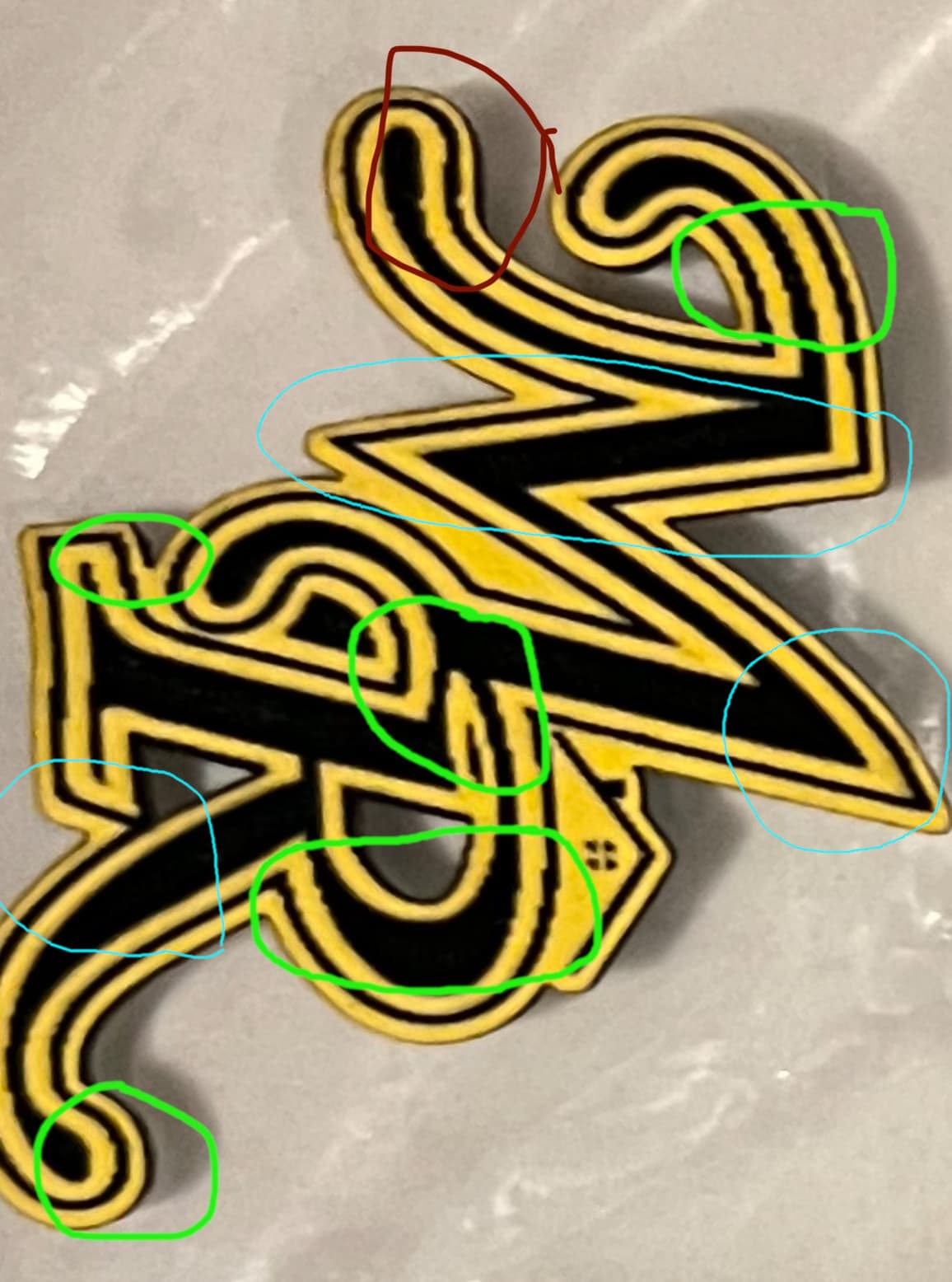
Lower right blue outline show little effect, but in the center of the scan I can see the issue. This doesn’t make sense as an acceleration or overscan issue… However, if these are rotated so the X and Y is swapped, we may have different things going on.
If this is correctly orientated and it’s doing this in scan mode, I’d think there is something binding the X axes in those areas with anomalies. Have no clue what that could be.
If I had to intentionally make that happen, I don’t know that I could do it via software…
Interval or dpi/lpi selection is critical to good results. Although I know you’re not photo engraving there is a lot of similarity when selecting the interval. Anytime you use a scan type operation, such as image or fill.
There is a Laser Everything video on photo engraving, although done on a fiber machine, the procedure works for any laser with any material. It will help you determine what kind of interval works best for your application, material and laser. They also have a bunch of good videos on their Youtube channel.
I think this video, will clarify some of your question and will be well worth the watch time. This is actually part 1 of 2..

Good luck
![]()
Ah my bad, one of the screen shots of your settings showed CO2. But anyways, you can try cutting the power down a bit, but not sure what material you’re using either. Like I said earlier, running some stencil tape across will help with the over burn, sometimes you can just wipe it off with alcohol. But I do know if you’re getting jagged lines you need to up the line interval or the image itself is to low resolution. If the image itself is to low, upping the line interval won’t help much. You’ll have to do some pain staking tedious modifications like just tracing the image then do some node editing to smooth out those lines into curves. Once you do that, up the line interval, maybe lower the power, max the air assist and it should improve
Can you upload the LBRN file that is causing the problem?
Yep here you go!
Test File.lbrn2 (125.6 KB)
At this point I am leaning more towards mechanical but I just gotta track it down
So when it was engraved it would’ve been rotated 90 degrees, I wonder if I have my belts slightly too tight and it’s missing a step on the Y axis? I’m going to adjust the belt tension tonight and run another test
Engrave part of the file looks good. The cut has a lot of nodes, but only looking at Engrave issues. When you rotate 90 degrees, you end up with shorter length engrave lines in the areas you noted. Did you try running it in the orientation of the file?
Yeah I meant 90 degrees from the picture @jkwilborn had posted, the file was ran as it, so are you thinking mechanical as well?
I know you know, but 90 degrees clockwise or counter clockwise?
If you’re going to post a help message about how these are working, you need to post photos in the correct orientation or at least advise which is which. If you don’t then, much of what we may think would, at minimum require an axes swap.
Most computers have graphic programs that allow you to rotate it and post it in the correct orientation. I use Gimp, it’s free and runs on all platforms I know of.
It’s more difficult to help, if the user posts the images sideways or inverted.
![]()
2 Likes
Send the file to the laser, ‘upright’, then send one that’s been rotated 45 degrees clockwise, then send one at 90 degrees rotation, and one at 180 degrees.
I’d like to see how & where the mess differs between one and the next.
It’s odd that it occurs in engraves as well as in vectors?
Yeah, this is a classic diode laser issue. You’re running 600 inches per minute at 50% power with 3 passes, and on most materials that works. But yellow? That’s where things fall apart.
Diode lasers use blue light, and yellow just doesn’t absorb that wavelength worth a damn. It reflects most of the beam instead of letting it dig in, so the laser’s basically skating across the surface. That’s why your lines are choppy and inconsistent even though your file is clean.
Here’s what I’d do if we were dialing it in together:
First, slow it down. Drop to 300 inches per minute, maybe even 250. You need that beam sitting longer on the surface to do its job.
Second, either bump the power up to 60%, or keep it at 50% and give it a 4th pass. Personally, I’d try slower speed first before jacking the power too much—avoid char.
If you’ve got air assist, make sure it’s on full. That’ll keep the cut cleaner and help get through any burnt crap on the edge.
And last tip—if you’re still not getting clean cuts, try putting a piece of black paper or painter’s tape under or over the yellow just in the test area. It tricks the laser into hitting something it can actually cut.
Your design isn’t the problem. The color is
1 Like