With this Test file:
Do you have notes to go with it by chance?
Eg. If Line A is longer than line B, then X stepper calibration needs changing, or backlash is on Y etc etc.
Cheers
With this Test file:
Do you have notes to go with it by chance?
Eg. If Line A is longer than line B, then X stepper calibration needs changing, or backlash is on Y etc etc.
Cheers
I have plenty of stepper motors around, but no suitable drivers on hand. I’ve ordered some, but it looks like they won’t arrive until Sunday so I won’t be able to test this until next week.
Once I prove that this is the issue I might try servos again and see if there is some way to get it working, but there is very little in the way of configuration options in the Ruida controller for handling this sort of situation so it might just come down to finding some motors that have lower latency, or finding a way to tune the motors themselves.
This is actually the 3rd type of closed loop motor I tried in the machine when I was still working on the mechanics. I also bench-tested 2 or 3 other styles and determined that they were not good enough. For the previous ones I tried I found too much ‘seeking’ and vibrating… In one case I think they could be tuned by connecting to a PC, but I couldn’t get serial cable to work. All of the ones I’ve tried though used the integrated controller ‘backpack’ on the motor. These really just use standard stepper motors with a magnetic encoder on the back part of the shaft. On my CNC machine I use some nema 23 motors that have integrated encoders on the motor and a stand-alone driver… I believe that type is available in Nema 17 so I might give them a go, I suspect they will be of much higher quality, but the two cables required tend to be unwieldy.
I’ll report back here next week. Thanks again everyone for the help.
Cheers,
Troy.
If you post your results and I’ll add notes to it.
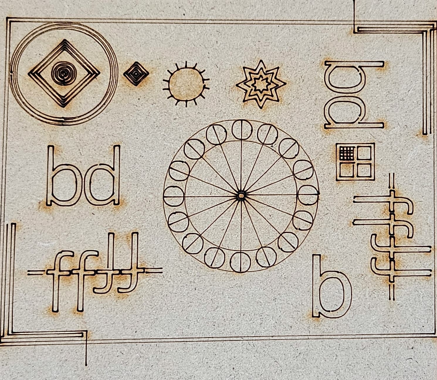
Here it is… there is a lot to unpick. The ‘star’ looks quite warped, the concentric circles loo spiral, the ‘sun’ shape is clearly not round… and the middle radial circles are all over the place. I ran this at 200mm/s 10% power in a piece of 3mm MDF without air.
Hopefully when the stepper drivers arrive I can try it again with plain steppers. I ordered what I believe are decent quality drivers, but who really knows when it comes to these things.
Cheers,
Troy.
i know is not the case, but if this was a diode machine and i was looking at it for diagnostics i would say imediatly
Y belts and X belts are loose ![]()
Curiouse about what causes this so will follow along!
Swinging a bit wild here, but do the belts and pinions have the same/complementary profile? If so, is it a low backlash profile?
Even without any potential motion control issues 200mm/s would be quite fast for these kind of line burns. Does dramatically reducing speed affect the outcome?
I suspect you’re running up against minimum power required for lasing to prevent burning but try what you can.
Yes, the belts are all properly tensioned. They are good quality 2GT belts and pulleys, the same type (and supplier) that I have used on a 3d printer and small CNC router in the past.
Cheers,
Troy.
We’ve seen this before…
Check out this thread… it also has a good thread in one of the responses. I saw a similar one the other day…
Good luck
![]()
Indeed, after berainlb mentioned that the closed loop servos could be the problem I did some searching and came to that thread - It sounds to me like I have exactly the same issue.
I thought it sounded familiar…
I have seen nothing on what exactly is happening or how to fix it.
If you figure it out, let us know or post a link…
Good luck
![]()
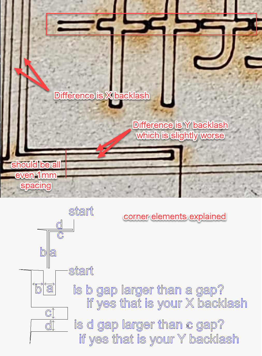
Most of the test relates to the shapes in the corners which are designed to reveal backlash by cutting parallel lines after a moving back from the opposite direction:
The other shapes like the ‘f’'s (which should all line up I discovered by accident seem to work well at highlighting backlash problems - you can see in yours that it is more uneven for the horizontally aligned f shapes which confirms the Y-axis backlash is a little worse.
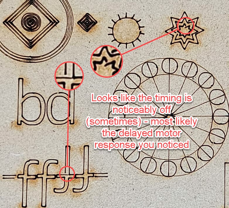
The other noticeable thing with yours which may confirm potential latency issues:
Hi Everyone,
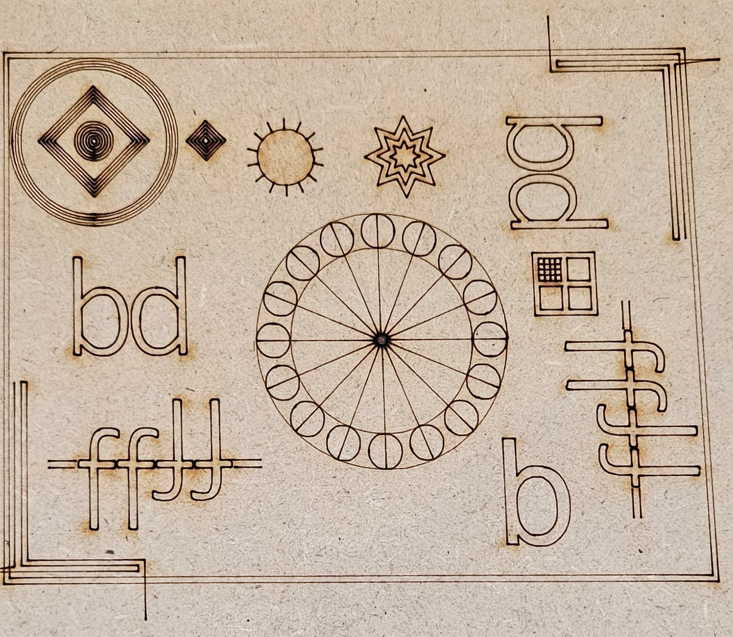
After changing out my closed loop steppers for some plain old (dumb) steppers and drivers I am happy to report that pretty much all of my issues are gone!
The top left concentric circles and diamonds still look a little funny… That may be due to my laser alignment not being absolutely perfect… but the rest of it looks much, much better. In particular, the main issue with the gaps between that start and finish is gone so I think timing issue that I had are resolved. The next thing to do is to try engraving again, hopefully I will not need a 4mm scanning offset anymore.
Thanks to everyone who contributed. I hope this thread is helpful for others that are considering using closed loop steppers. It would be nice if we could resolve the issues so that closed loop motors can be used but there are only two ways that seems possible to me - either we need closed loop motors that are much, much faster… or Ruida needs to add the ability to input a pulse delay compensation, which would require precisely measuring the latency of the motors (which could be difficult).
Cheers,
Troy
Just an update - it seems that this has not resolved my huge scanning offset. It looks like I still need around 4mm at 300mm/s… So my laser tube / power supply must be responding quire slow as well… In any case, at least I can compensate for that so it’s not a huge issue, but it just brings me back to my original question - Is it normal to need such a big offset? or does it indicate a possible issue with my laser or power supply? Should I be concerned that something is not right in it?
Thanks,
Troy.
Glad you’re making progress.
The scanning offset is on the large side although I’ve seen others report similar values at times. This could be related to the driver that you have. What specific drivers and motors are you using?
Also, what specific laser power supply are you using? I tend to think it’s not going to be an issue with the LPS if it’s otherwise functioning normally. Have you changed the frequency of the laser PWM signal on the Ruida?
Hi,
The LPS is:
Power Supply: Cloudray HY-Z Series Z100 (Cloudray 100-120W AC90-250V HY-Z Series Z100 CO2 Power Supply(With/Wit – Cloudray Laser )
The motor drivers I’m using now are DM542T Version 4.0 from StepperOnline (https://www.omc-stepperonline.com/digital-stepper-driver-1-0-4-2a-20-50vdc-for-nema-17-23-24-stepper-motor-dm542t)
The motors are some generic 60mm long Nema 17 200 step motors.
Since these are different motors and drivers and the scanning offset values are pretty much identical to the last motors / drivers I’m pretty sure it’s not the drivers now. My start/end points now match up perfectly and circles are perfectly round. The scanning offset has to be either my power supply, the laser, or the Ruida controller itself. Mind you, I did play with the pwm settings on the Ruida before when I was trying to figure out my issues…
All in all it’s working fine now with the scanning offsets inputted the results are very nice.
What a huge difference!
4mm line shift at 300mm/s I would not consider a problem at all. This is not necessarily a slow responding ps and tube - as this calibration is mostly related to compensating for the multitude of time varying parameters involved with every part of the motion generation.
If you’re reading this, don’t discount closed loop steppers entirely as the Thunder Nova 24 I’m running has them and they’re working fine. They are not the integrated driver type that you had though. If not pressed for space why cram the driver which generates a lot of heat in with the motor which also generates a lot of heat?
If you set your ‘Min Power’ value down a little that would stop the overburn in the corners and start/stops.
I had my min/max power both at 10% for those runs. The minimum I can do is about 8%. Any less than that and the tube doesn’t fire at all.
You don’t mention speed that you’re running, that I remember.
I’d suggest a wider range of min/max. If it can lase at 8%, use that for minimum and see if you can get 11% for max to be used… speed change? You have to be careful with higher speeds with details in vectors.
If you do this, you need to ensure the controller is set correctly… These are limits. When the speed at or below the start speed, only the minimum power used.
Probably forgot something… ![]()
Don’t forget to save a copy of the vendor setting of your controllers setting in the Machine Settings gui. You can always recover with the original vendor setting.
Have fun
![]()