We recently bought an A5 Pro from CL or Marketplace and I just did this last week.
I followed this LB video: (I think he’s a LB staff person)
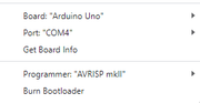
I followed that video exactly and it worked fine. Then lookup his LB “flash firmware” video (if you go back in the LB video history it’s right around same time as that first video I linked). Just follow the instructions exactly and it’ll work fine. My Atomstack A5 Pro (board v1.5) was exactly the same as everything he said on the otur laser in the video.
I had one hiccup: My coordinates needed to be changed to -399 x -409. But then when I saved my config and re-flashed the firmware to keep or save the settings permanently, I flashed and told the laser that where I wanted to be 0,0 (front left) was still -399 x -409. So when I tried to cut anything (for example an object at 25,25), the laser head was trying to crash off the back right… Because I told it that the front left was -399 x -409 so then the back right must be 0,0 and to cut something at 25,25 it needs to keep going outside the area of the frame. When you re-flash just don’t forget to set 0,0 where you really want it to be.
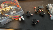
Amazon doesn’t let her & I share our account. Looks like I bought the safety glasses and the honeycomb worktable… And she must have bought the limit switches. I believe we bought these:
https://www.amazon.com/HiLetgo-Endstop-Mechanical-Switch-Printer/dp/B012IBU1NO/ref=sr_1_1_sspa?crid=WN11IZLZJJMO&keywords=endstop+limit+switch&qid=1697726923&sprefix=endstop+s%2Caps%2C88&sr=8-1-spons&sp_csd=d2lkZ2V0TmFtZT1zcF9hdGY&psc=1
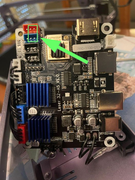
They worked fine, no need to change the pins, etc. They plug right in and are fine as they come wired. You don’t need to delete the 3rd (power) wire, all that does is turn on the LED light when the limit switch is triggered. Only problem is the plug connectors at the board aren’t exactly correct (mentioned in the video), and also the wires are too short. They need to be another 8-12 inches longer (200mm-300mm).
Last comment:
I used this from Printables:
https://www.printables.com/model/296152-atomstack-a5a5pro-limit-switch-mounts
It’s a little misleading in the description. It says you need to “drill/tap” --they aren’t talking about drilling or tapping the metal extrusion/frame of the Atomstack, they mean in the 3d printed plastic parts so you can screw the endstops into the plastic mounts you print.
Hope that helps.
I have this:
20231012_grbl_configs.txt
$$
$0=10
$1=25
$2=0
$3=0
$4=0
$5=0
$6=0
$10=0
$11=0.010
$12=0.002
$13=0
$20=0
$21=0
$22=1
$23=3
$24=100.000
$25=4000.000
$26=250
$27=1.000
$30=1000
$31=0
$32=1
$100=80.000
$101=80.000
$102=250.000
$110=6000.000
$111=6000.000
$112=1000.000
$120=1000.000
$121=1000.000
$122=10.000
$130=410.000
$131=400.000
$132=200.000
ok
and also here’s the (bad version, I still need to find how to correct the -399 x -400 value) config lbset file:
{
“Name”: “GRBL”,
“Settings”: [
{
“Desc”: “Status: Position reporting ($10)”,
“ID”: “0xa0000”,
“Value”: “Workspace Position”
},
{
“Desc”: “Status: Show buffer data ($10)”,
“ID”: “0xa0001”,
“Value”: false
},
{
“Desc”: “Junction deviation (mm) ($11)”,
“ID”: “0xb”,
“Value”: 0.009999999776482582
},
{
“Desc”: “Arc tolerance (mm) ($12)”,
“ID”: “0xc”,
“Value”: 0.0020000000949949026
},
{
“Desc”: “Report inches ($13)”,
“ID”: “0xd”,
“Value”: false
},
{
“Desc”: “Soft limits ($20)”,
“ID”: “0x14”,
“Value”: false
},
{
“Desc”: “Hard limits ($21)”,
“ID”: “0x15”,
“Value”: false
},
{
“Desc”: “Homing cycle ($22)”,
“ID”: “0x16”,
“Value”: true
},
{
“Desc”: “Homing feed rate (slow) (mm/min) ($24)”,
“ID”: “0x18”,
“Value”: 100
},
{
“Desc”: “Homing seek rate (fast) (mm/min) ($25)”,
“ID”: “0x19”,
“Value”: 4000
},
{
“Desc”: “Homing debounce (ms) ($26)”,
“ID”: “0x1a”,
“Value”: 250
},
{
“Desc”: “Homing pull-off (mm) ($27)”,
“ID”: “0x1b”,
“Value”: 1
},
{
“Desc”: “Max spindle speed (RPM), S-Value max ($30)”,
“ID”: “0x1e”,
“Value”: 1000
},
{
“Desc”: “Min spindle speed (RPM), S-Value min ($31)”,
“ID”: “0x1f”,
“Value”: 0
},
{
“Desc”: “Laser mode enable ($32)”,
“ID”: “0x20”,
“Value”: true
},
{
“Desc”: “Step pulse (microseconds) ($0)”,
“ID”: “0x0”,
“Value”: 10
},
{
“Desc”: “Step idle delay (ms) ($1)”,
“ID”: “0x1”,
“Value”: 25
},
{
“Desc”: “Step enable invert ($4)”,
“ID”: “0x4”,
“Value”: false
},
{
“Desc”: “Limit pins invert ($5)”,
“ID”: “0x5”,
“Value”: false
},
{
“Desc”: “Probe pin invert ($6)”,
“ID”: “0x6”,
“Value”: false
},
{
“Desc”: “X Step pin invert ($2)”,
“ID”: “0x20000”,
“Value”: false
},
{
“Desc”: “X Direction pin invert ($3)”,
“ID”: “0x30000”,
“Value”: false
},
{
“Desc”: “X Homing direction invert ($23)”,
“ID”: “0x170000”,
“Value”: true
},
{
“Desc”: “X Steps per mm ($100)”,
“ID”: “0x64”,
“Value”: 80
},
{
“Desc”: “X Max rate (mm/min) ($110)”,
“ID”: “0x6e”,
“Value”: 6000
},
{
“Desc”: “X Accleration (mm/sec^2) ($120)”,
“ID”: “0x78”,
“Value”: 1000
},
{
“Desc”: “X Max travel (mm) ($130)”,
“ID”: “0x82”,
“Value”: 410
},
{
“Desc”: “Y Step pin invert ($2)”,
“ID”: “0x20001”,
“Value”: false
},
{
“Desc”: “Y Direction pin invert ($3)”,
“ID”: “0x30001”,
“Value”: false
},
{
“Desc”: “Y Homing direction invert ($23)”,
“ID”: “0x170001”,
“Value”: true
},
{
“Desc”: “Y Steps per mm ($101)”,
“ID”: “0x65”,
“Value”: 80
},
{
“Desc”: “Y Max rate (mm/min) ($111)”,
“ID”: “0x6f”,
“Value”: 6000
},
{
“Desc”: “Y Accleration (mm/sec^2) ($121)”,
“ID”: “0x79”,
“Value”: 1000
},
{
“Desc”: “Y Max travel (mm) ($131)”,
“ID”: “0x83”,
“Value”: 400
},
{
“Desc”: “Z Step pin invert ($2)”,
“ID”: “0x20002”,
“Value”: false
},
{
“Desc”: “Z Direction pin invert ($3)”,
“ID”: “0x30002”,
“Value”: false
},
{
“Desc”: “Z Homing direction invert ($23)”,
“ID”: “0x170002”,
“Value”: false
},
{
“Desc”: “Z Steps per mm ($102)”,
“ID”: “0x66”,
“Value”: 250
},
{
“Desc”: “Z Max rate (mm/min) ($112)”,
“ID”: “0x70”,
“Value”: 1000
},
{
“Desc”: “Z Accleration (mm/sec^2) ($122)”,
“ID”: “0x7a”,
“Value”: 10
},
{
“Desc”: “Z Max travel (mm) ($132)”,
“ID”: “0x84”,
“Value”: 200
},
{
“Desc”: “A Step pin invert ($2)”,
“ID”: “0x20003”,
“Value”: false
},
{
“Desc”: “A Direction pin invert ($3)”,
“ID”: “0x30003”,
“Value”: false
},
{
“Desc”: “A Homing direction invert ($23)”,
“ID”: “0x170003”,
“Value”: false
}
]
}
If there’s a way to email or upload this stuff as attachments I can do that too.