Hello, thanks for info, I have done more research on how relays and TTL signals work. just to reassure myself that i wont fry my control board.
Yes I plan to get a DB15 breakout board. You can get them with one or both male and female DB15 connectors. I plan to mount a two connector version and a relay onto a piece of plywood using brass standoffs and then stick the whole lot inside a suitable resealable plastic box,
And to help avoid the joys of stray strands of copper I will be using my crimping tool to add a connector to the end of each wire. I need to validate the purchase of the crimping tool and wire stripping tool.
And to ensure the cables are not accidently pulled out, I will use heatsrink on the wires that poke out through a vent hole of the laser source/control boards enclosure and then use a cable gland. Course once warrenty expires I will install keyed sockets.
I am using the heat shrink to make the wires thick enough that the cable gland can properly clamp onto the wires. This goes on the inside of the enclosure stopping the wire being pulled out of the connector if the wire is accidently snagged on the outside the enclosure.
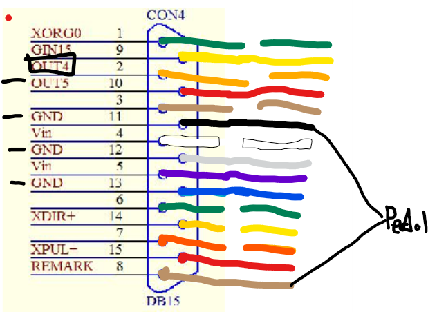
The laser has two buttons on the head which turn the frame lasers on and off and the second button marks the project. the second button and foot pedal are both wired to pins 8 and 11. I will have to see what the first button is wired to. It isnt going to be of any use once i install the enclosure after all.
Is it safe to splice into any ground wire? they are all taken up.
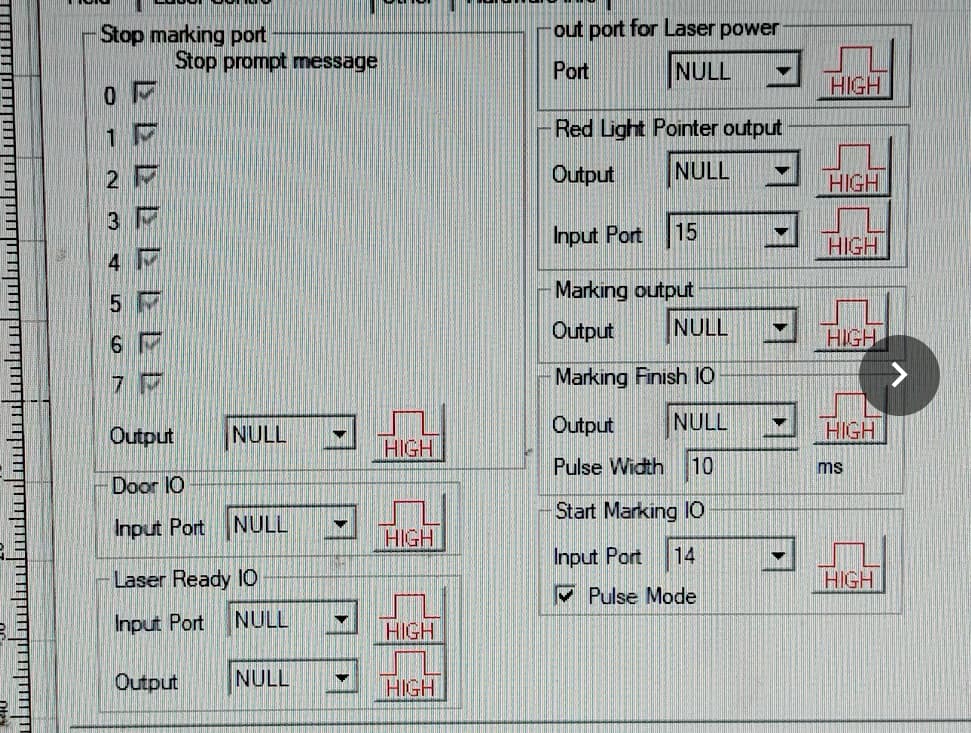
Well i did some more checking and the buttons on the lasers head dont do anything until ezcad2 is started. Have to say i am a bit surprised as the position numbers do not correspond to the pin out of con4 at all. I moved the Red ouitline button setting to door enclosure and the laser refused to fire unless the button was held down.
So I plan to use for lights:
Vin, pin 4 to Relay DC+
GND, pin 11, 12 or 13 to Relay DC-
OUT4, pin 2 to Relay IN
And for interlocks:
GIN15, pin 9
GND, pin 11, 12 or 13
Hopefully nothing minds sharing a ground pin. Its odd how there are more things to pair with a ground pin than ground pins.
Don’t know what buttons… mine only has power for the focus leds, that I don’t use.
It does make sense, I understand when you run something the configuration file is reloaded to the controller… so it may be kind of dumb controller… This is from memory reading about it on this site somewhere…
It’s not uncommon to have one ground and multiple feeds… can be inconvenient though.
The problem is are these optical isolated inputs, so the associated ground is required…?
I’ve never been in mine, so I don’t know how these really work. Never have had me scope on it.
My one is supposed to double as a hand held fiber laser so it has a button to turn on the red laser framing and another to mark the project. They are just momentary switches. Course you would have to be crazy to use it as you need to lug around a super heavy laser source, computer and the fiber from the source is too short. Also good luck holding the heavy laser head still for more than a few seconds. truly a pointless gimmick. I only got it as it seemed well made at a good price.
But yeah you can assign the function under IO ports in the basic settings tab in Lightburn, maybe you could reassign the button on your lasers head to something more useful to you.
As for combining grounds, its easy for me to do since I am using a breakout board to attach extra wires, it’s just the fear that it wont like it. You hear about making ground loops with audio equipment generating electrical hum on computers and so on. Wouldnt want something weird happening here too that may cause false signals or damage the circuit board. I dont know enough about it and would like to experiment as little as possible with my laser.
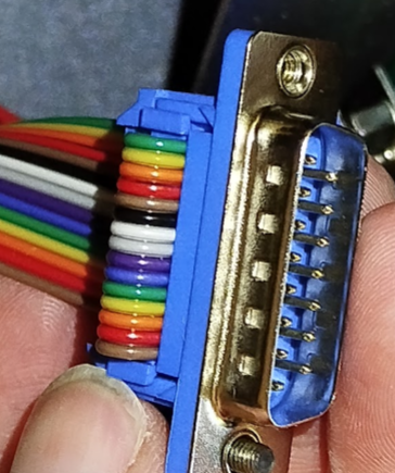
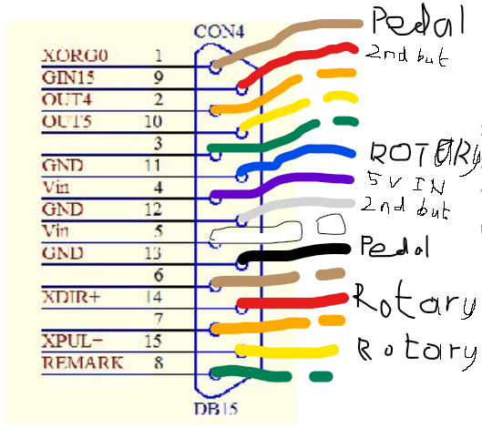
looking at what pins I had the rotary going to making no sense, I double checked and noticed I had the pic of the ribbon cable upside down compared to the socket pin out drawing.