JPT MOPA Fiber laser with safety enclosure

Hello all.

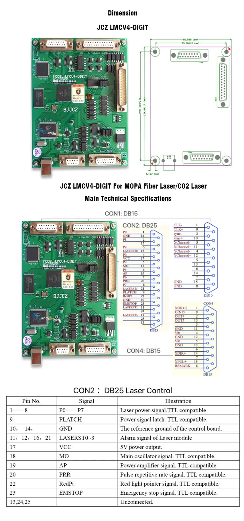
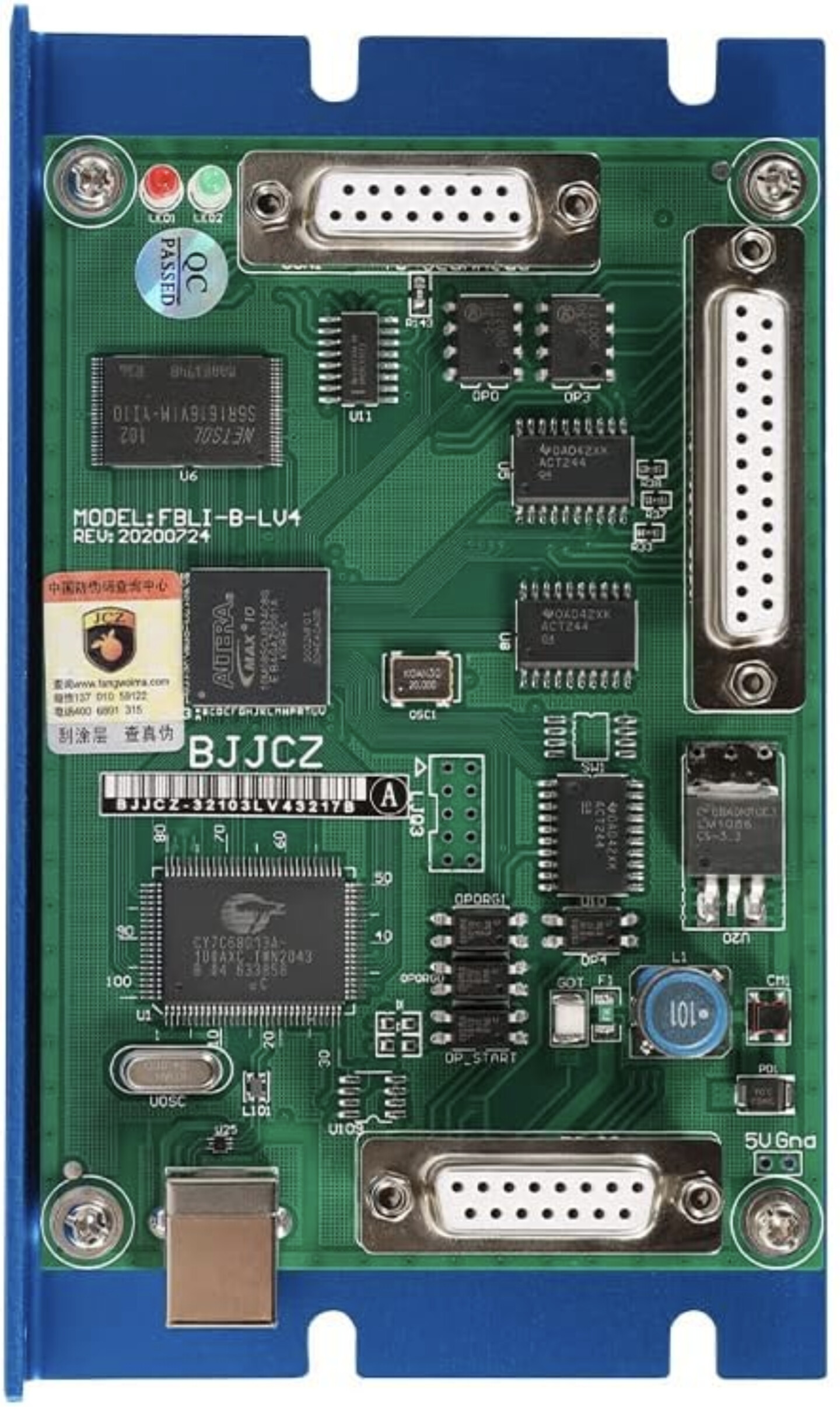
I am planning to buy a laser engraver with an enclosure. It uses the LCZ-LMCV4 control board. Does anyone have any personal experience with this laser or enclosure, or have a recommendation for a better machine? This will be used in a production environment, sometimes with the larger 300x300 engraving area, so I wanted to get a high wattage machine for fast cycle times. I would appreciate any tips/feedback on this setup.

https://www.amazon.com/Marking-Machine-Engraver-Marker-300×300mm/dp/B086GDLHMC/

https://www.amazon.com/Cloudray-Protective-Compatible-800mm-Lift/dp/B09MZ8JDX2

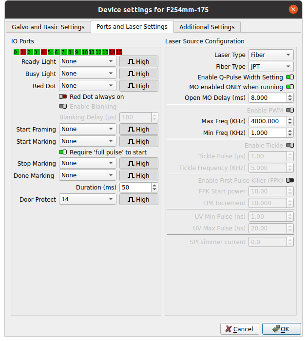
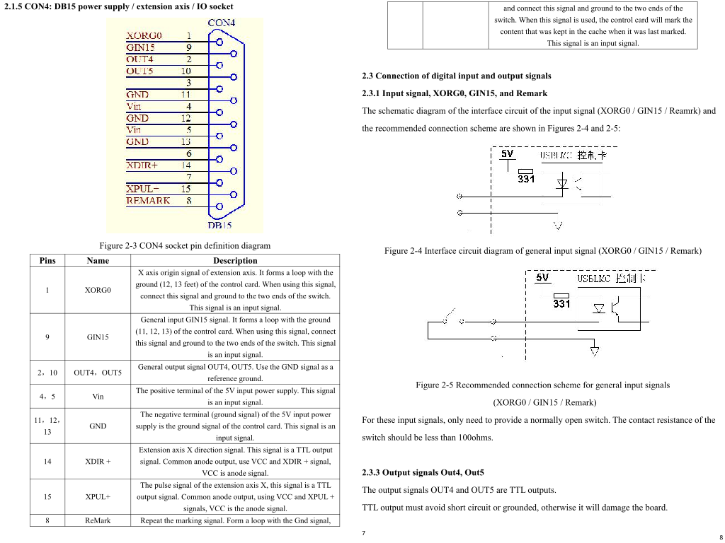
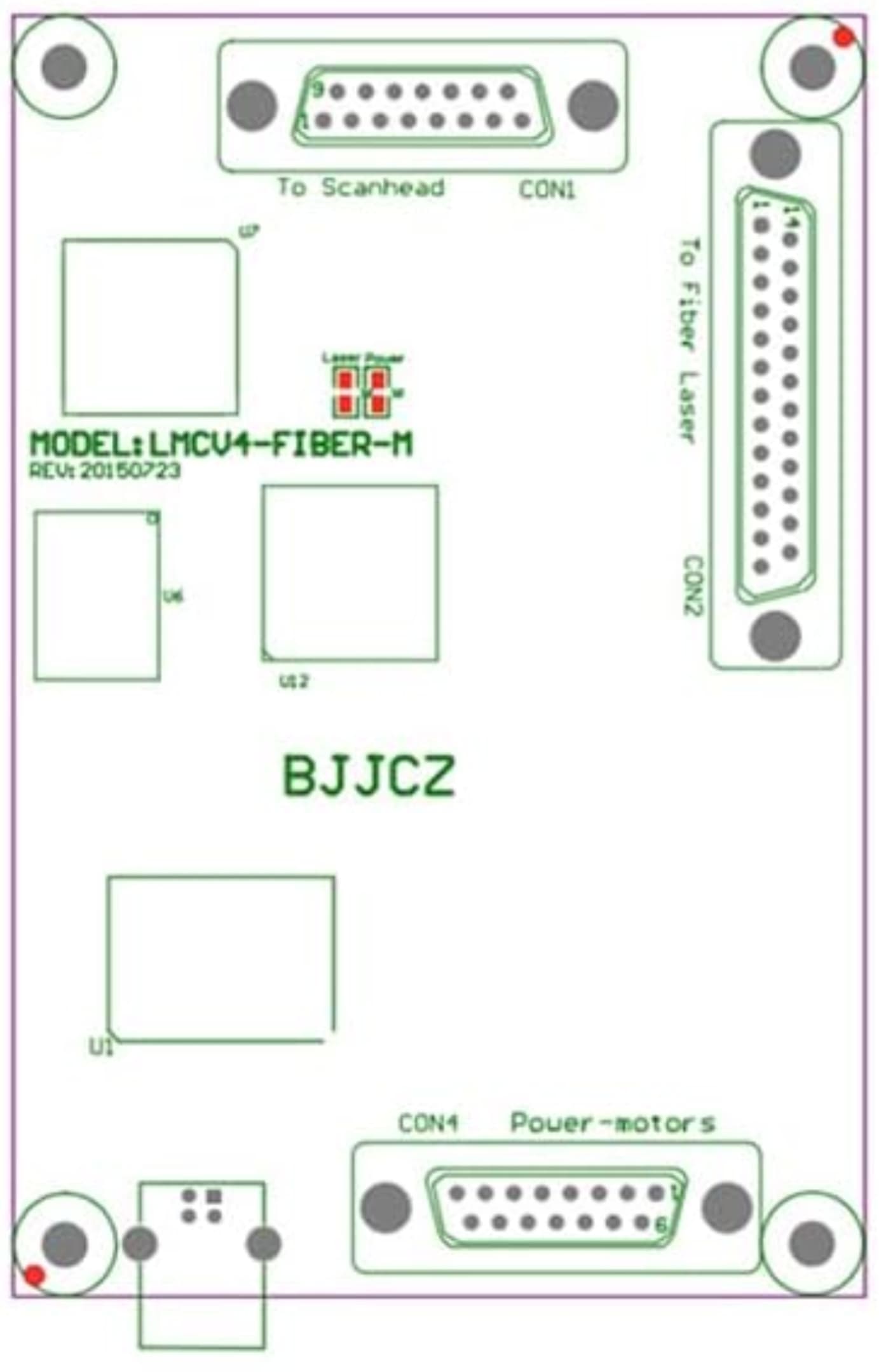
I would like to add a simple door interlock safety switch. Could anyone please advise how this will work with Lightburn? I’ve found that I can use pin 15 for the “door protect” setting in lightburn, but I can’t find any information online about how to wire this pin up to the control board.

Further, I can’t find any information about how this will work exactly. Will opening the door while the laser is on just disable the laser and continue engraving? Or will it act like an E-stop? Will I be able to use the tracer preview function while the door is open? I haven’t been able to find any documentation regarding this function.

Thanks,

An e-stop should disable all power to the machine. If it’s an emergency, you can’t foresee what the emergency is, if so, you should have fixed it. The proper/safe way is to remove power from the whole machine.

I changed my MOPA foot switch start marking to door protect in the device settings.

When running a job and I step on the switch, it will pause the work. I can click resume in Lightburn to continue. Probably what you want… you’d have to deal with how the operator would know this is what’s stopping it from lasing.


Where you actually wire this is a bit of a question. There is conflicting or not clear information on where you actually wire them into the controller… Notice they only identify three of the five connectors.

I found this, uniquely alone, so don’t know if this is the same model of board or not… seems to cover most of the missing i/o pins…

Probably be wise to ask the vendor of your machine how to wire this up, they might actually be useful and answer you …

I’m sure we’d all like to know, so don’t keep it a secret… :crazy_face:

I haven’t opened mine up yet, but I’d start by following the foot switch wires…

:smile_cat:

1 Like

So, I just installed a door interlock and alert lighting on my fiber laser… I couldn’t find any documentation (and “support” didn’t grok the question at all), but I found a “Safety Enclosure” for my brand on eBay that had a wiring harness for contextual lighting, a door interlock, and a basic fan. I figured I may as well buy it for the parts and knowledge. (I stripped the parts from the enclosure and used them on mine – definitely wasn’t going to use the orange plastic pieces with no certification markings instead of my full enclosure with dark green certified 12"-ish window that cost as much as their entire enclosure.)

On my controller, apparently a “BJJCZ FBLI-B-LV4” (IIRC), there is a DB15 connector labeled something like “CON4 Power-motors”. I see the same connector and pinout on other ezcad2 boards for which I could find manuals online, e.g. “LMCV4-FIBER-M”. That connector is the one that exposes the few useful pins that carry the few signals I had to work with.

  • Pin 1, XORG0, was connected to my existing foot switch.
  • Pin 9, GIN15, was where the new door interlock switch connected.
  • Pin 2, OUT4, was heading off into the cable bunch to the tower, and I didn’t bother with it, but it’s likely doing something, I guess?
  • Pin 10, OUT5, was wired to a signal-level relay that connected power to some LED lighting (switching which of the R, G, and B buses on the LED strip were lit).
  • Pin 8, REMARK, looks like it could potentially be useful for some people (run whatever’s cached again), but I didn’t bother with it.

So, I connected everything up, and then I just had to go into Device Settings and configure a few things on the Ports and Laser Settings, page. Specifically, for me:

  • Busy Light: 5 (High)
  • Start Marking: 14 (High)
  • Door Protect: 15 (High)

The door interlock prevents you from starting the job, and if a job is running, it immediately pauses. (It’s a door interlock, which is what I wanted, not an e-stop, which the machine already had.) Also, it does not have any effect on framing. What’s even more useful to me is the LED lighting. When the machine is on, I have it wired to be a nice green (both inside my enclosure and also outside lighting the handle), and when the laser is active, I have it set to be a nice bright magenta.

I so appreciate having a visual indicator, especially for cleaning passes that sometimes barely show at all (or any completely invisible off-nominal out-of-focus lasering). I also made sure I built the enclosure and installed the door interlock so that it functions well before there are any clear gaps.

2 Likes

Thanks… do you have a photo of your board identifying the proper connector? Most of the ones I have lack a connector or two…

Thanks for the input…

:smile_cat:

I pulled these off the net, but they’ll do. My controller is identical to the photo (except without the Cloudray blue tray and sticker), and the diagram shows the labels that are obscured by the connectors on the board.

The DB15 to note is the one next to the USB cable, i.e. the one opposite the scanhead connector and its two status LEDs.

1 Like

Thanks to both of you for the great info! Hopefully this thread will help others.

ClayJar, could you send me the “enclosure” you purchased for reference? I’m not planning to use it, just to find similar parts. Could you describe how the input/output wires are added to this harness? I’m assuming you used the DB15 cable that plugs into CON4, so did you have to strip this cable and splice on connectors? Or are there labels wires/connectors on this cable? I would probably plan to make this myself with a breakout board.

If I’m reading this all correctly, the output signals output 5V DC and the input signals just require to be connected to ground (normally open)? So any door/foot switch and 5V LED should work?

In my case, I ended up buying this for the parts, as with it and other documentation and info I had already acquired, I could figure out how things work. I certainly wouldn’t recommend it.

So, getting down to the useful info… The DB15 connector in the machine was a standard screw-together clamshell connector with only certain pins connected to a wiring squid (different ones going in all different directions). In my case, there were already wires soldered to pins 9 and 10 (GIN15 and OUT5, respectively), and there was already a connector on the back of the machine to feed them out, but that was just delightful convenience.

For GIN15, i.e. pin 9 on the DB15, you can just connect a switch between it and any of the several grounds on the connector. (To use a powered non-contact switch, you’ll also need to tap Vin or another source, of course, but you could also use a simple magnetic door switch.) GIN15 is internally pulled high, with the normally open switch shorting it to ground.

For OUT5, i.e. pin 10 on the DB15, my system had the coil side of a 5V signal-level relay (specifically, a HSINDA 941H-2C-5D – Amazon link) connected between OUT5 and GND. The switched contacts on that signal relay were used to switch the LED lighting. (You would not want to try to drive the lighting directly from a signal pin, of course.)

The LED strip I salvaged from the enclosure (using significant amounts of brute force – that thing is never ever getting back together) was the kind with separate red, green, blue, and ground/common bus bars, so it was just a matter of connecting power to the color channels I wanted lit. It would be just as easy to use the signal relay outputs to feed a stack light, but I had the LED strip, so I used that.

So, to summarize: Input pins float high and use a normally-open switch to short to ground. Output pins can use a signal-level relay (or an Arduino, or a Raspberry Pi Pico (W) if you level shift them) to do whatever you want.

Are these relays switching anything but the led indicator…

Found the data sheet and it says these relays draw about 30mA… that should drive most ss devices.

Just curious… Mine went out of warranty a few months back and I still haven’t opened it up…

:smile_cat:

Thanks, that makes sense. I will probably use a 5v relay board with pin OUT5 to control the busy light, XORG0 to read the foot pedal, and GIN15 for the door interlock, as you did. Using some cheap hardware similar to the stuff below:

https://www.amazon.com/AEDIKO-Channel-Optocoupler-Isolation-Support/dp/B095YD3732/

It would be nice to also have a ready light as well, so I’ll tinker with the output pins and report back if I find a working combination for the pins. I should have the machine in a few weeks and I’ll report back. Thanks for the help!

In my machine, there was just the one lonely little signal relay with some double-sided foam tape sticking it down, and it was just there to switch the lighting based on OUT5.

Sounds about right… :crazy_face:

If it draws 30mA, there are lots of ways to switch stuff with that kind of power… Wonder is the led even draws that much…

Did you notice if it had a snub diode across the coil?

:smile_cat:

I didn’t bother checking the draw of the LED strip, but there was something like a meter, meter and a half, of RGB tape, so I’d wager it’s drawing well over 30mA to drive the strip. (It’s some decently bright stuff.)

As for a snubber diode… drat! I didn’t do anything to the signal relay, so I completely let it slip my mind that, of course, I should have added a snubber diode while I was in there. Well, it’s easy enough to open up and add one, and I think I remember where I put my Amazon-ordered diode multipack from when I upgraded the air assist on my CO2 laser.

Didn’t think of a strip. Thinking single led… I usually put a ssr in there…

I bought a 1k piece bag of 1N914 small signal diodes half a decade ago, still have a boat load of them

:smile_cat:

I like your style!

It’s amazing what you can get away with when the patient need not survive the operation. :grin:

1 Like

Hello,
Now this was what I was looking for, So I just need to attach the interlock switch to pin 9 and an unused ground pin to make the interlock work.

I have just bought a ComMarker B4 30w fiber laser and it should be with me within a month. Seeing as I like my eyes (poor as they are) I have decided to use aluminium extrusions and aluminium sheets to fabricate an enclosure with a slide up door that makes 3 out of the four sides slide out of the way.

My laser comes with a FBLI-B-LV4A control board (if the online manual is accurate) and I was looking everywhere online on how to attach the interlock. I am thinking of adding a extension cable onto the DB15 cable and splice on to or redirect the appropriate wires.

Having read this thread I have a sudden desire to add indicator lights for my convenience. However I have no idea what signal the control board sends out for the lights or how the lights can be made to react to these signals.

Could you please tell me how to wire in this functionality please?

To make things simple, you could take advantage of the widespread existence of parts for Arduino-type projects these days. Specifically, an opto-isolated relay board like this cheap pair for $8 on Amazon looks like it should do what you want right out of the box: HiLetgo 2pcs 5V One Channel Relay Module Relay Switch with OPTO Isolation High Low Level Trigger

To use that to switch lights, you’d just have to connect between its terminal blocks and some of the pins on the DB15 (using the pinouts from post #3, above in this thread):

  • Relay IN → OUT5 (DB15 pin 10)
  • Relay DC- → GND (DB15 pin 11, 12, or 13)
  • Relay DC+ → Vin (DB15 pin 4 or 5)

Then connect two lights through relay side:

  • COM (whatever’s feeding the juice to your lights)
  • NC (your “laser not currently blasting away” light)
  • NO (your “DANGER, WILL ROBINSON!” light)

(The other side of the lights then just commons back to the other side of whatever is powering the lights.)

Then it’s just telling the controller that the busy light is port 5 (High) as in post #3.

Thanks alot :slight_smile: That’s everything I needed to know. Oh I cant wait for my laser to arrive.

Though looking through the thread again, one thing has me slightly concerned, On the third post with the page from a manual, it mentions at the end in section 2.3.3 that OUT4 and OUT5 are TTL outputs and not to ground them or it would damage the board. Looping it through an opto-isolated relay board definitely wont break the laser control board right? I know on the relay board it shows it going through a fixed value resistor on the schematics on the back of the board but I dont know enough about circuits to know if this is enough to keep the control board happy.

According to the datasheet on the simple relay used to switch the lights in my machine (a relay that was part of the machine as built and shipped to me), at 5V it draws 29.9mA. The relay board example I linked says in the listing the trigger current is 5mA, which is 1/6th of the draw compared to the one in my machine (which is because the relay board is powered separately from the signal pin, hence needing three connections on the input side). I don’t have a datasheet on the controller (which is how all this started for me), but I figure if something is well within the capabilities of the GPIO pins on a Raspberry Pi Pico or Arduino, it should be just fine for the controller (and the factory-installed relay on mine is six times thirstier).

Now, if you wire it all up and set the bare relay board on a metal part of the inside of the case, shorting everything out… well, that would be a bad thing. Be careful with your wiring (no George Michaels), and put the relay into a nice plastic shell of some kind. (I don’t recommend just using 3M VHB tape to stick it to something, but I’m not going to say I’ve never done that… although for something expensive, maybe I’d stick it to some acrylic and then stick that down… but I have multiple lasers and a 3D printer or two to avoid the temptation.)

(I believe it’s bigclive that taught me about George Michaels, e.g. shorts from leaving a careless whisker when using stranded wire.)

A little tip- I’m planning to use this breakout board for tapping into the input/output pins. That will avoid having to strip an extension cable and splice the wires.

(it won’t let me post the link but just search Amazon for “DB15 breakout board”)