I just installed an awesome tech board (M3) for my k40. Install was easy but I am having trouble with lightburn.
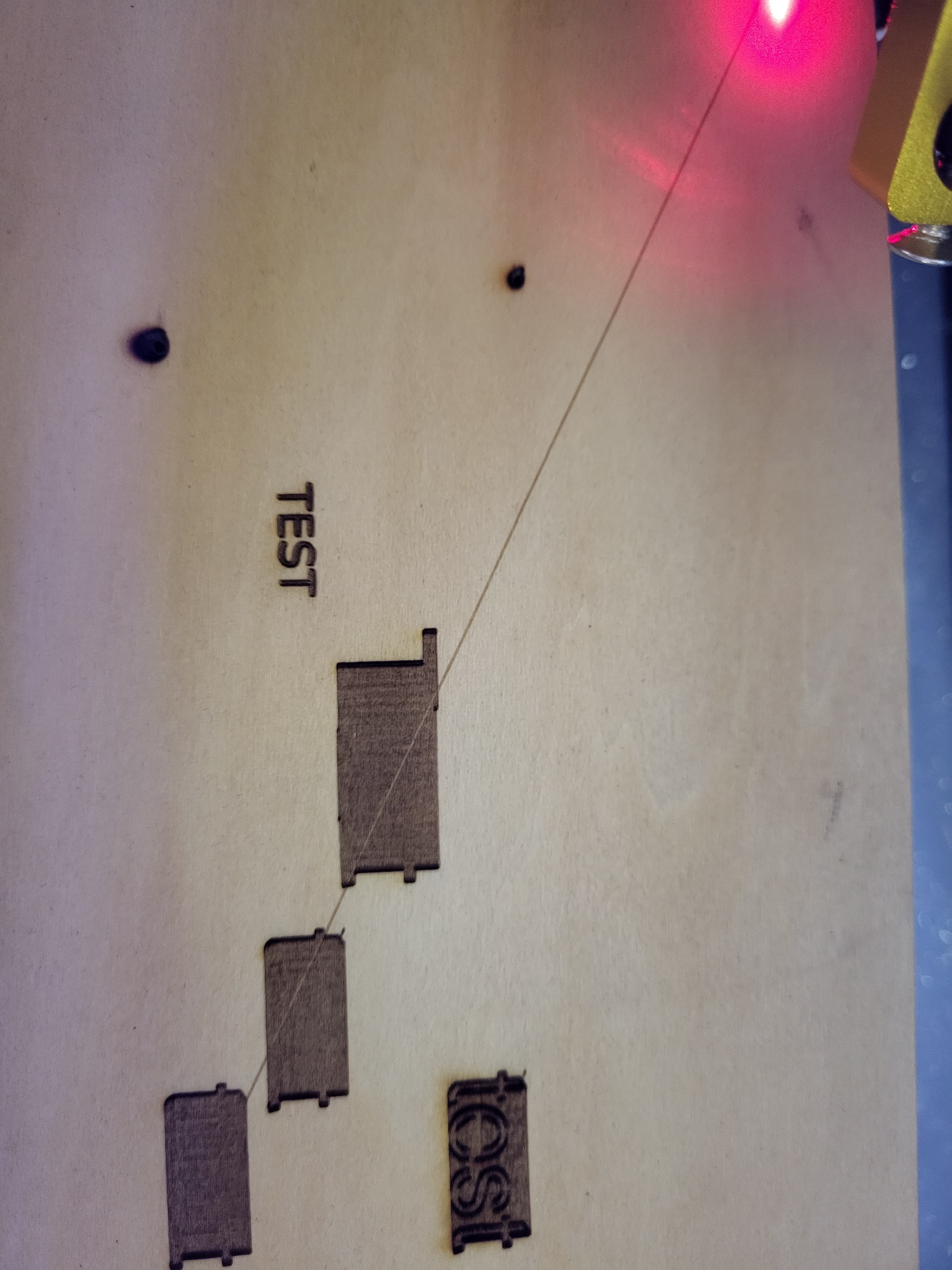
It is engraving the transverse lines. I double checked that laser mode was enabled ($32) which is set to true. I even disabled and enabled but that didn’t work.
I am not new to lightburn. I have a 100w co2 eith ruida controller, a 30W fiber laser and a diode all using lightburn. I can’t seem to figure this out.
I did test the laser prior with k40 whisperer and it engraved just fine. . The only other thing I can think of is maybe the driver for the board needs to be updated. I looked at awesome tech’s site but the instructions assume that a person knows how to install a .hex file from a command prompt. Which I don’t (though I could probably figure it out)
Attached are pictures of what the problem is and my current settings.
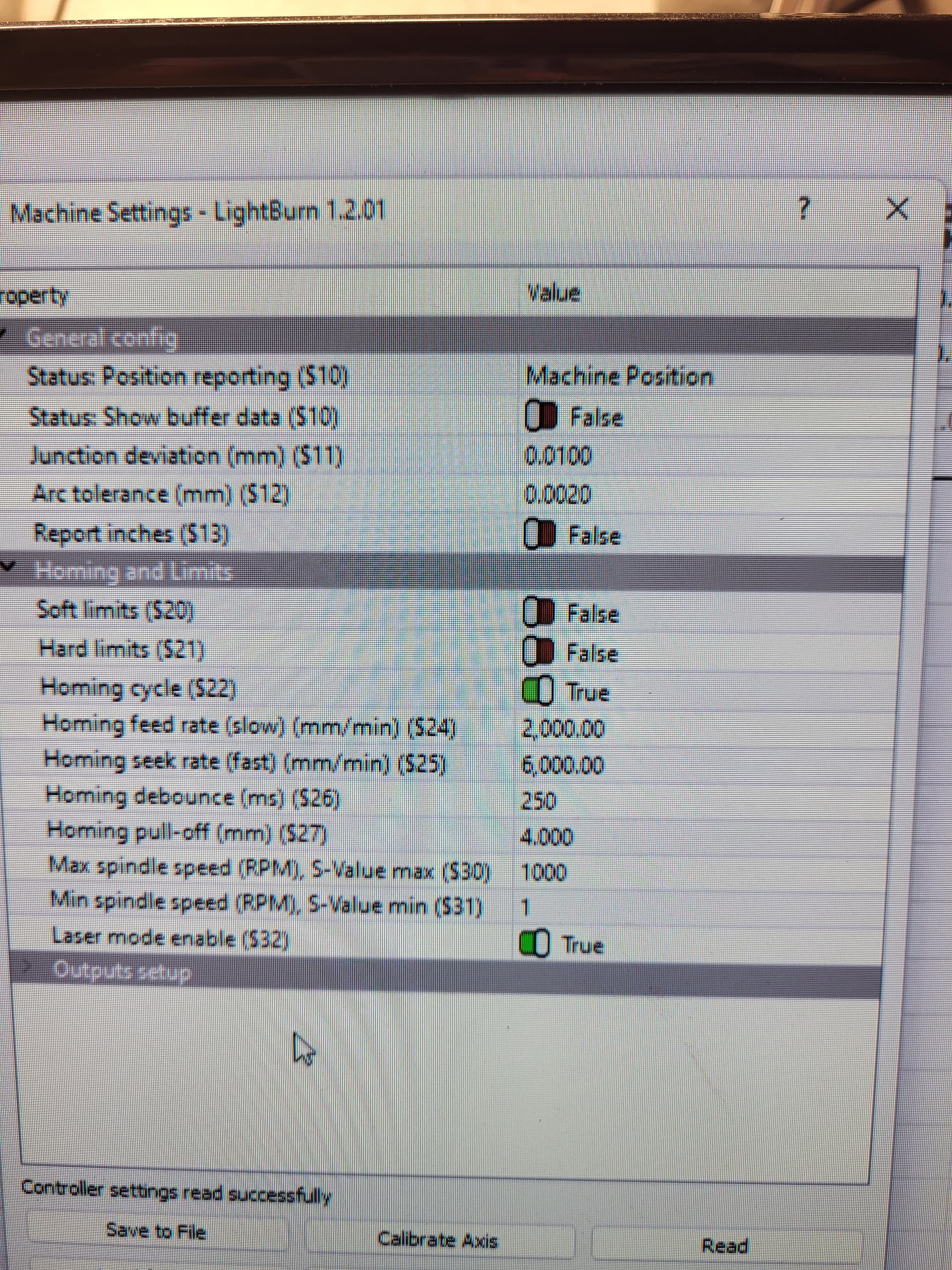
I’m not sure about this but these boards also control spindles, it looks like it thinks it’s getting the spindle up to speed…
![]()
Could this be a hardware or software issue?
This is usually not being in Laser mode with the grbl value of $32=1
I have one of these boards but have not spent any time with it, so I’m mostly speculating…
![]()
There are a few other settings or conditions that could engrave traverse lines but $32 set incorrectly remains the most common.
It’s possible from the pic that the PWM signal is inverted (or connected to the wrong power supply trigger) making 0% and 100% backward to each other.
When this happens the device engraves at 100% while traversing, 50% while being commanded to engrave at 50% and engraves at 80% power when asked to engrave at 20% power. Some CO2 High Voltage power supplies provide an option to use a Logic Low trigger or a Logic High trigger to fire the laser. So if this is what’s happening, and the power supply has this option, it’s a matter of moving the control wire to the other (logic low or logic high) trigger.
The fastest test I can think of would be to engrave something small/quick at 100% and see if you get nothing.
Changing speeds can add ‘scanning offset’ and do strange things like that but power level shouldn’t cause this.
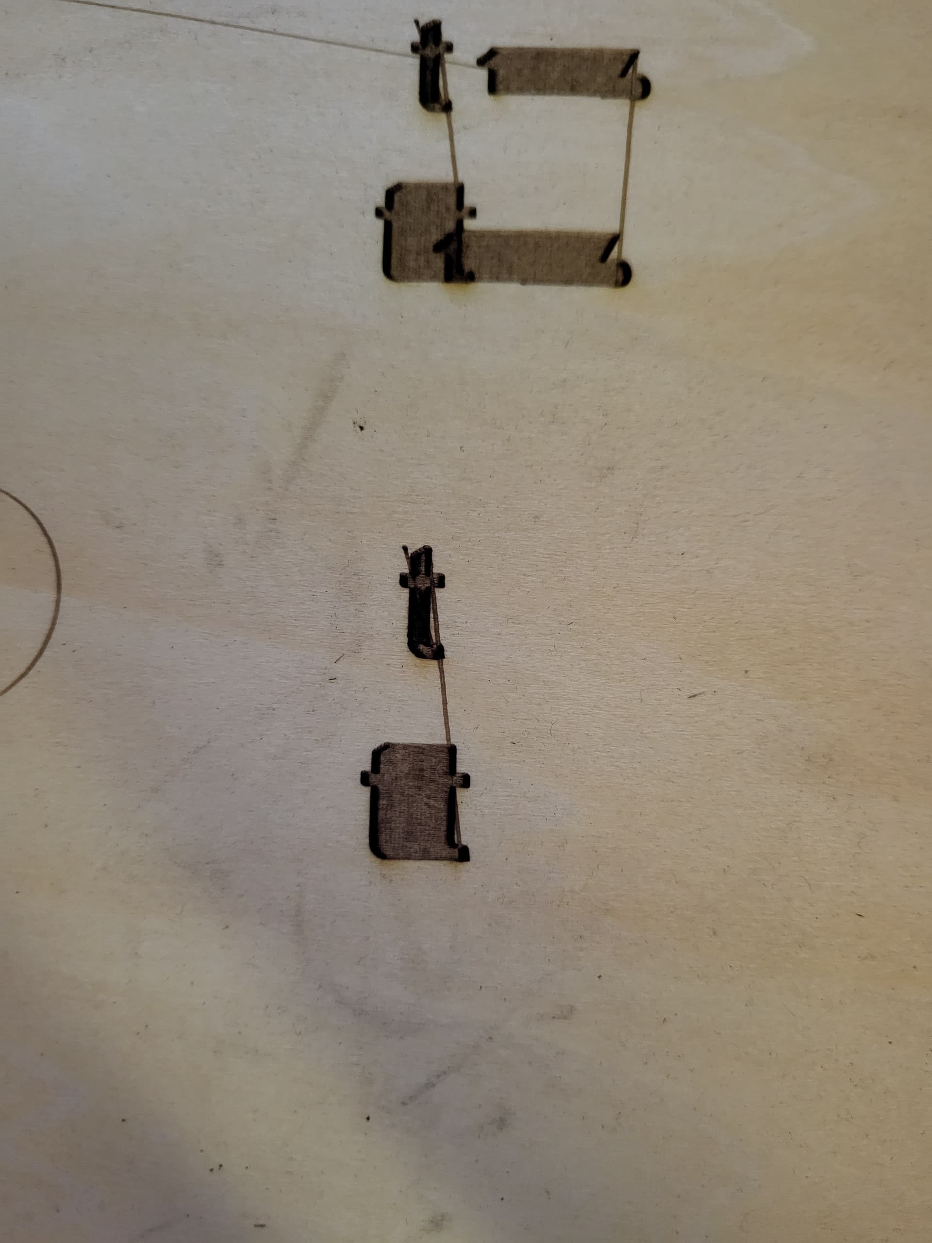
Please test with a simple shape like a small circle, square or something not filled.
It looks too clean to be random interference or power supply problems.
I did see that the scan offset was set to 2.5, i disabled it and that worked somewhat. I changed the fill to “fill shaped indiually” and it engraved like it should.
Here is a simple square. The transverse lines aren’t showing on line.
I noticed another issue though. It seems that no matter what i change the power to, it goes at 100% (i assume, i dont have an ma meter on it yet)
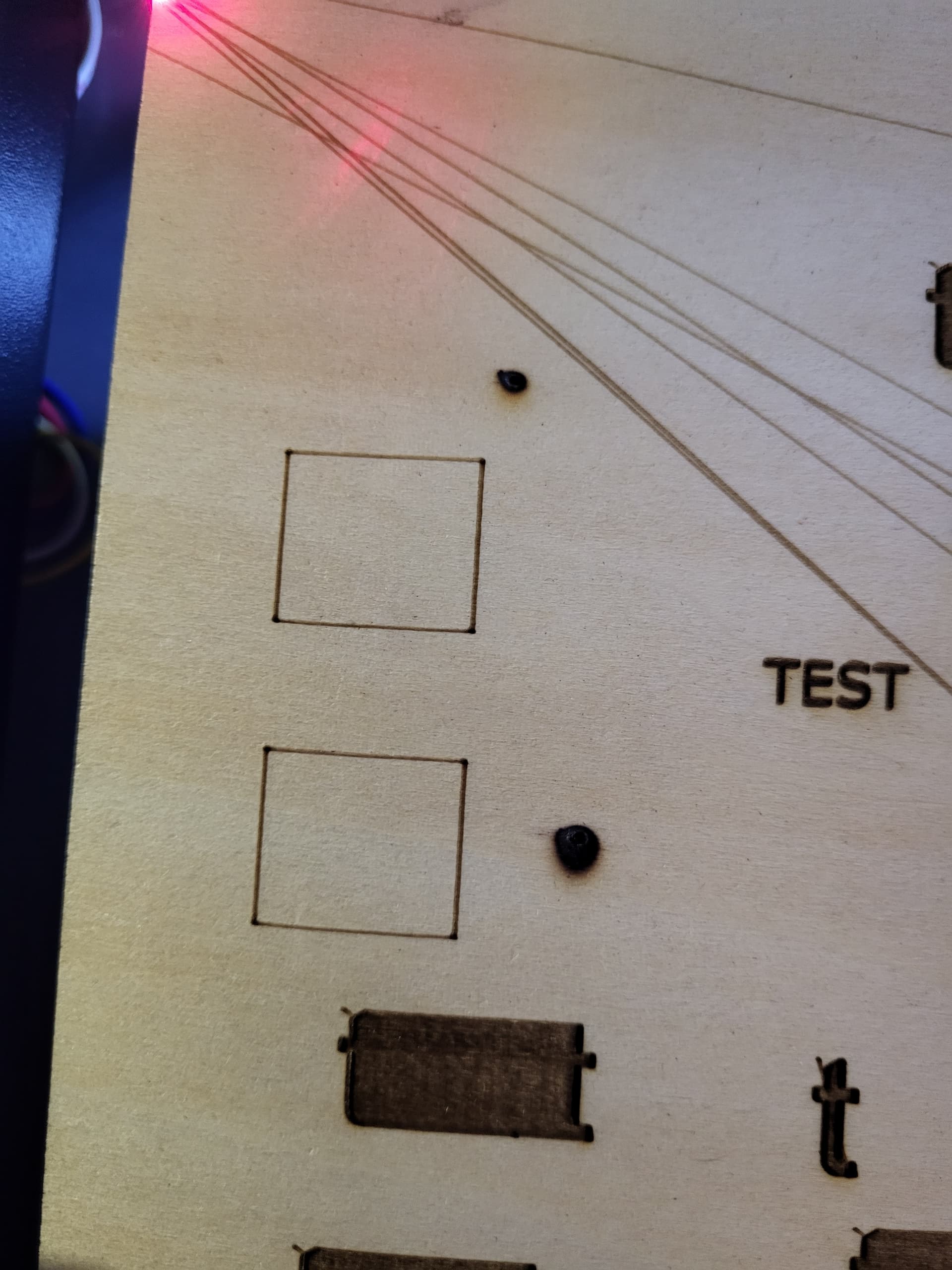
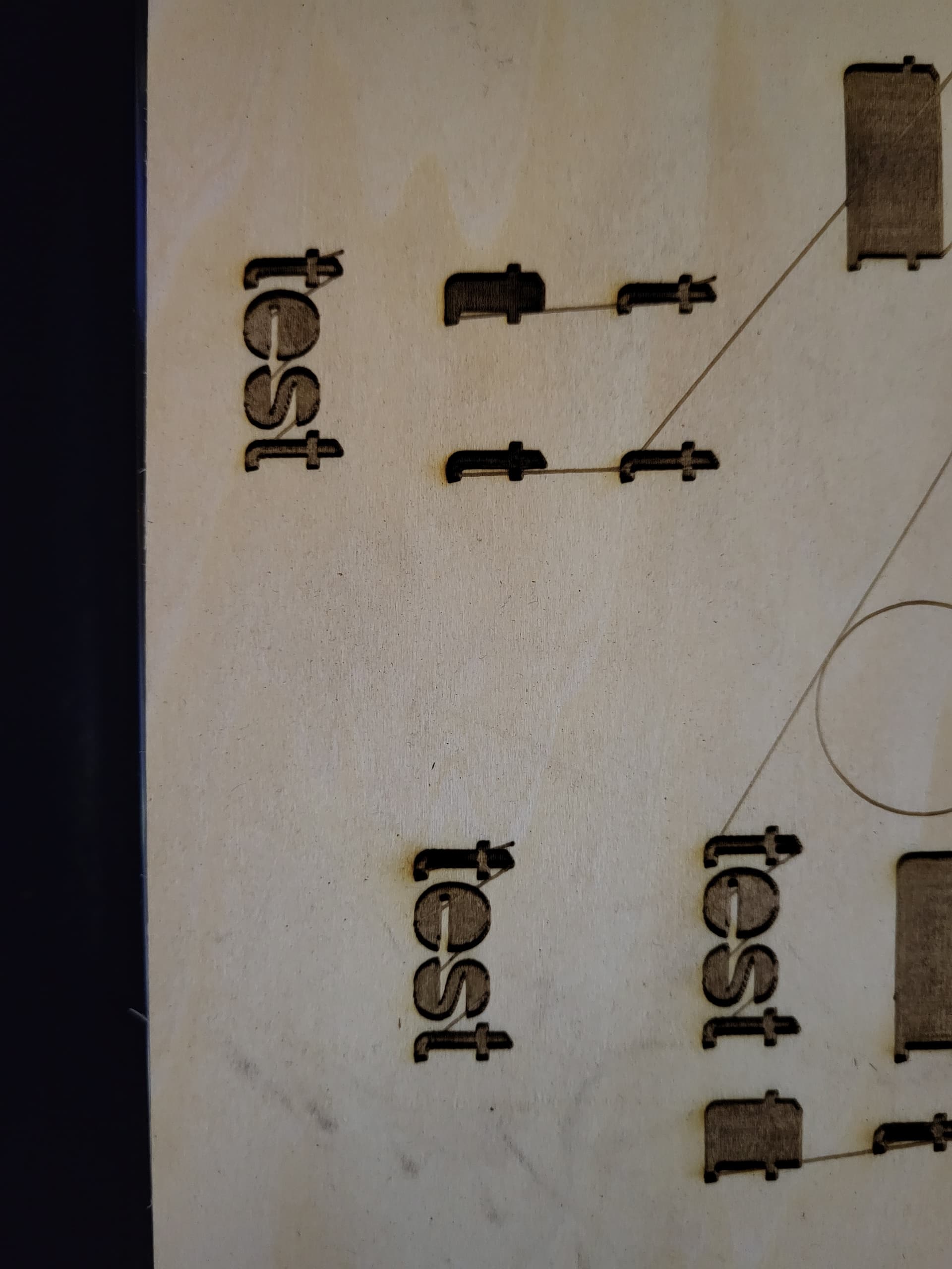
Twst was done at 100% & 5% in lightburn, they look exactly alike
It just might be me, but your lines look out of focus… not that it’s going to fix the problem… just thought I’d mention it…
How is the interface between your m3 board and the lps?
Have you measured the pwm output to see if it varies?
![]()
Yeah focus is most likely off but i can easily fix that.
The wire connecting the m3 noard to the power supply serm loose now that i started looking. It was originally a 3 pin jst connector on the psu but the new wire is just a dingle with a female end. I am asking my son who owns a computer repair shop if he can make me a better one.
I am going to have to ask my husband to measure the uutput, i dont know how to do that yet.
I’m glad you appended ‘yet’… ![]()
I doubt these ever will be a really user friendly type of machine… the more you can pick up, the quicker you can usually get it going again…
If you can remove power from the lps, it’s wise, there is no need to have it powered up to check the voltages of these interface lines… In fact I’d suggest you not power it up…
You can measure the output of the pwm signal with a voltmeter. It reads rms values and a ttl pwm control line will read 50% of the voltage at 50% pwm. If it’s 5V ttl then the pwm for a 50% setting should read 2.5V.
Disable the lps if possible and just change the power lever to change the pwm and run it to check the voltage…
You can change this on the fly with the power adjustment, I think it’s in the move window when the job is running.
Good luck
![]()