Do this in two steps:
- Adjust the step/mm distance
- Measure the actual kerf
Measure the distance moved using an accurate scale. I used the red-dot pointer on a steel scale:
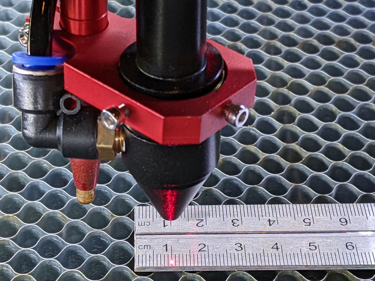
Lacking a pointer, you could measure the distance between two pulsed holes in paper or some such. The key concept is that the distance does not depend on actually cutting a shape; you can estimate the center of a dot or hole very accurately.
A few iterations of the calibration routine should get you very close to the right answer.
Once you have that for each axis, never change it. It is a property of the machine axis, not the lens or cut or power or anything else.
Then use a kerf measurement tool to find the cut width in whatever material you’re using. Apply half that value as the kerf adjustment in the Cut Editor or Offset tool.
That should get you as close to perfect as you need to be.