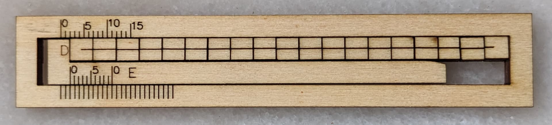
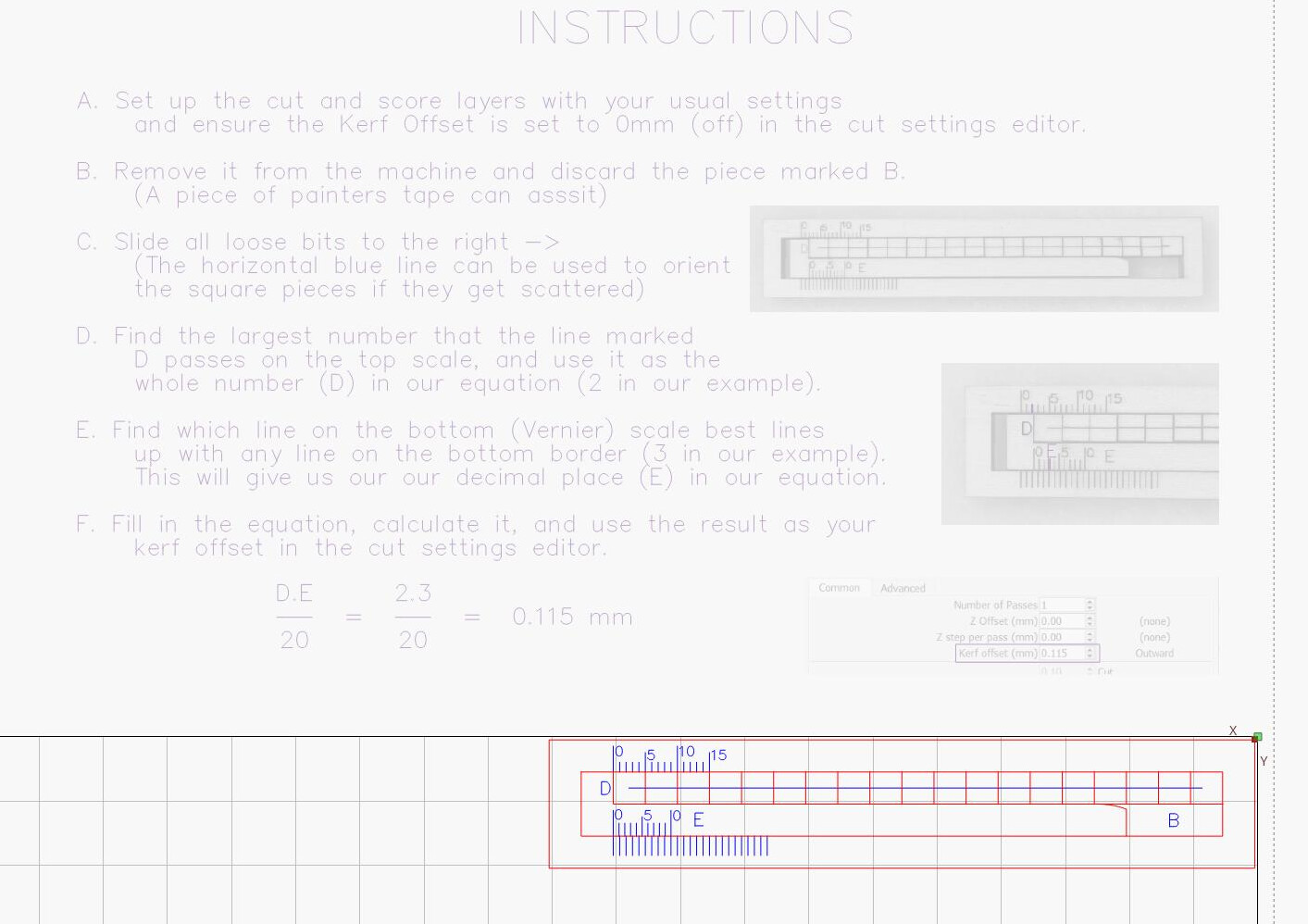
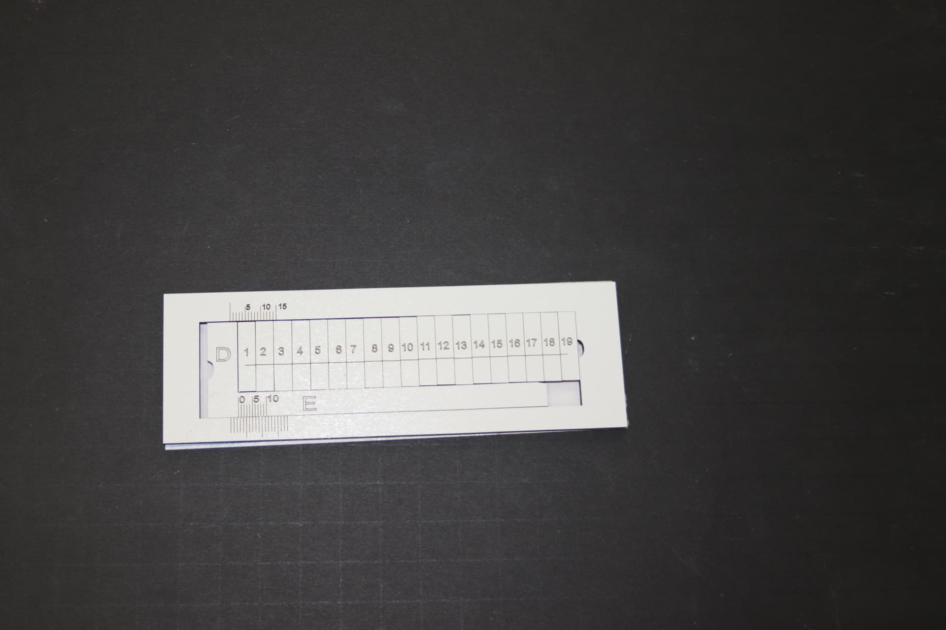
There has been a bit of a flurry of marquetry lately on the forum, and it prompted me to make a tool to help calculate kerf offset accurately and easily, while using minimal material:
I was inspired by @jkwilborn’s tool, but I added a vernier scale to make it easier to measure, without needing calipers! Just cut it, slide it, and calculate your kerf.
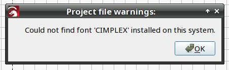
Odd! I was quite sure I converted all the text to paths. I must have missed something! I’ll check it over in the morning.
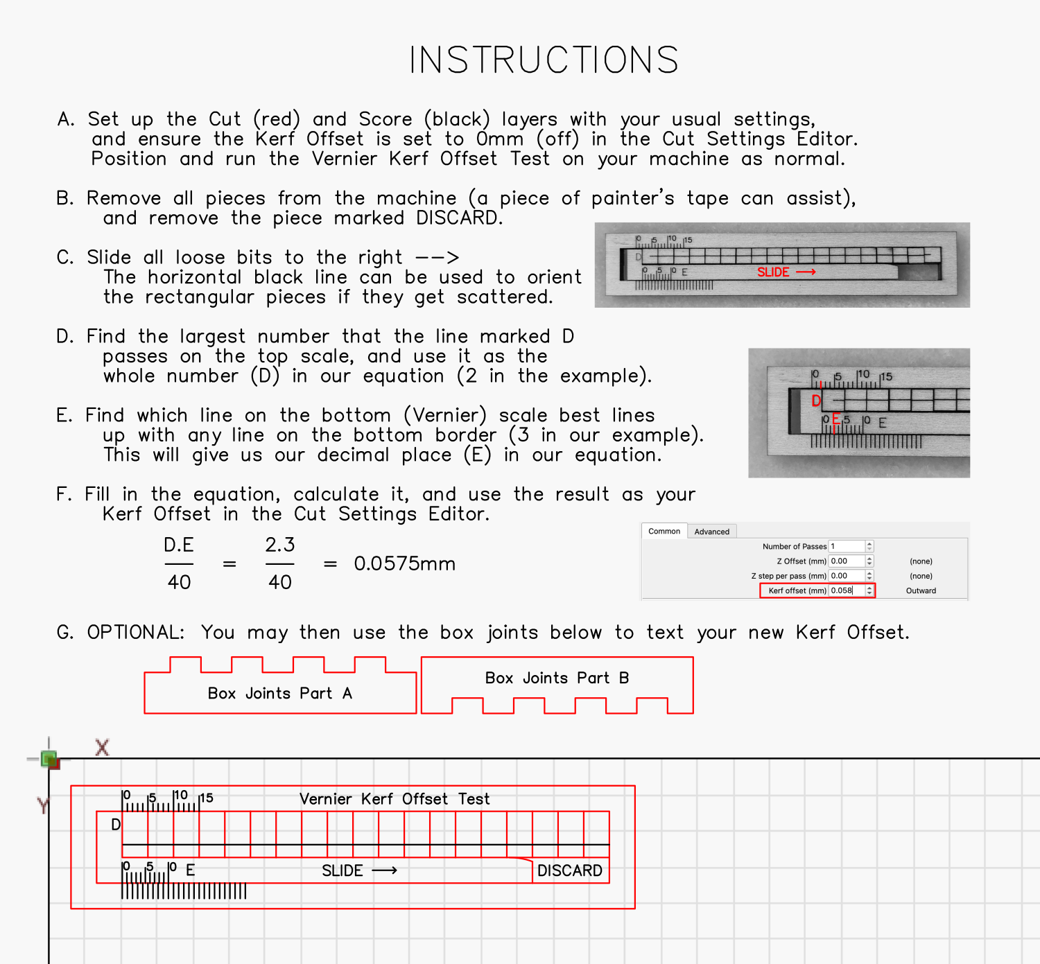
I struggled with the instructions. As a tool layer the lines were dotted, and thus hard to read plus I couldn’t put images on a tool layer. And as normal layers I was worried people would cut them if I didn’t have them set to not output, plus it was hard to see the annotations on the images. I could have used the notes function, but the instructions are rather long and I was worried folk wouldn’t remember it all/wouldn’t know how to reopen them, and the pictures compliment the instructions which I can’t add to the notes.
Would love some suggestions though! Thank you so much for the feedback! I really appreciate it.
Perhaps put (another copy of?) the instructions in Project Notes so they show up when the file opens. Not quite as convenient being on-screen all the time, but they’d definitely be more readable.
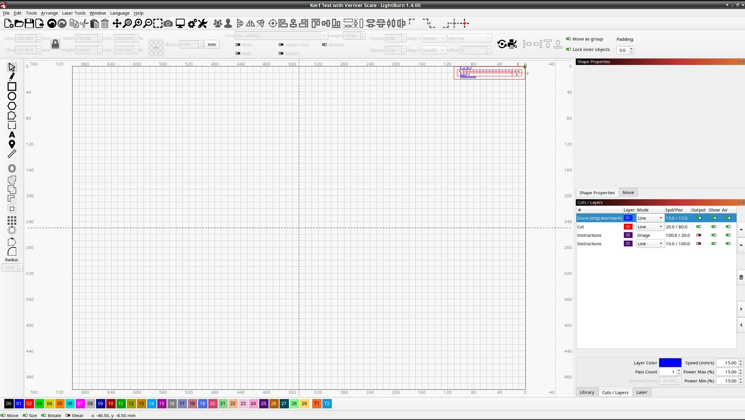
With my usual set of cut optimizations, the planner finished the vernier scales, cut the outline to drop the whole thing into the chip tray, then blithely (tried to) cut the squares.
So I twiddled the cut priorities to do the squares first, balanced some chipboard over a smaller tray, then Released The Laser:
This is all wonderful feedback thank you! I really really appreciate it! I’ll mention the priorities and add the instructions to the notes as well. Love the craft stick idea!
I thought about mentioning that you could lay some aluminium foil (matte side up) under the test to catch the pieces but I was worried it might also dissipate heat. I’ll have to test a bit.
Ooh! I’ll study up that link you sent about software testing too! Thanks again!
Thanks for the file, my experience is the same as earlier posters. The first time I ran it (on 3mm birch ply) all the squares fell into the honeycomb, so I repeated with the 3mm ply on a sacrificial 6mm piece…the tiny pieces still managed to fall out as I moved it. Is there any reason they are soooo small? If it could be enlarged so that each piece is big enough to handle easily that would help (I’m guessing that a small increase in the block size may have a bigger impact on the size of the tool?)
I have a xtool D1 non pro 10W and my measured was 1.4, giving a kerf offset of 0.07
my experience is the same as earlier posters. The first time I ran it (on 3mm birch ply) all the squares fell into the honeycomb
I had thought that ednisley was meaning that the piece the blocks were cut from fell through before they were cut into separate blocks, which is a problem because the focus would then be different, but I could have misunderstood!
I have been dawdling, but I’ll duck to the store shortly and grab some aluminium foil, I reckon that will provide a good backer to stop them falling through, and it will make negligible difference to the focal length.
I repeated with the 3mm ply on a sacrificial 6mm piece…the tiny pieces still managed to fall out as I moved it.
Just wanted to check, were you picking it up with the painters tape?
I’m guessing that a small increase in the block size may have a bigger impact on the size of the tool?
Yeah, that was my thinking. I could maybe make them longer in the vertical direction. Or make the tool less accurate and have just 10 pieces. Maybe I could offer a few versions?
Thank you so much for testing it and providing feedback! It’s really helpful!!!
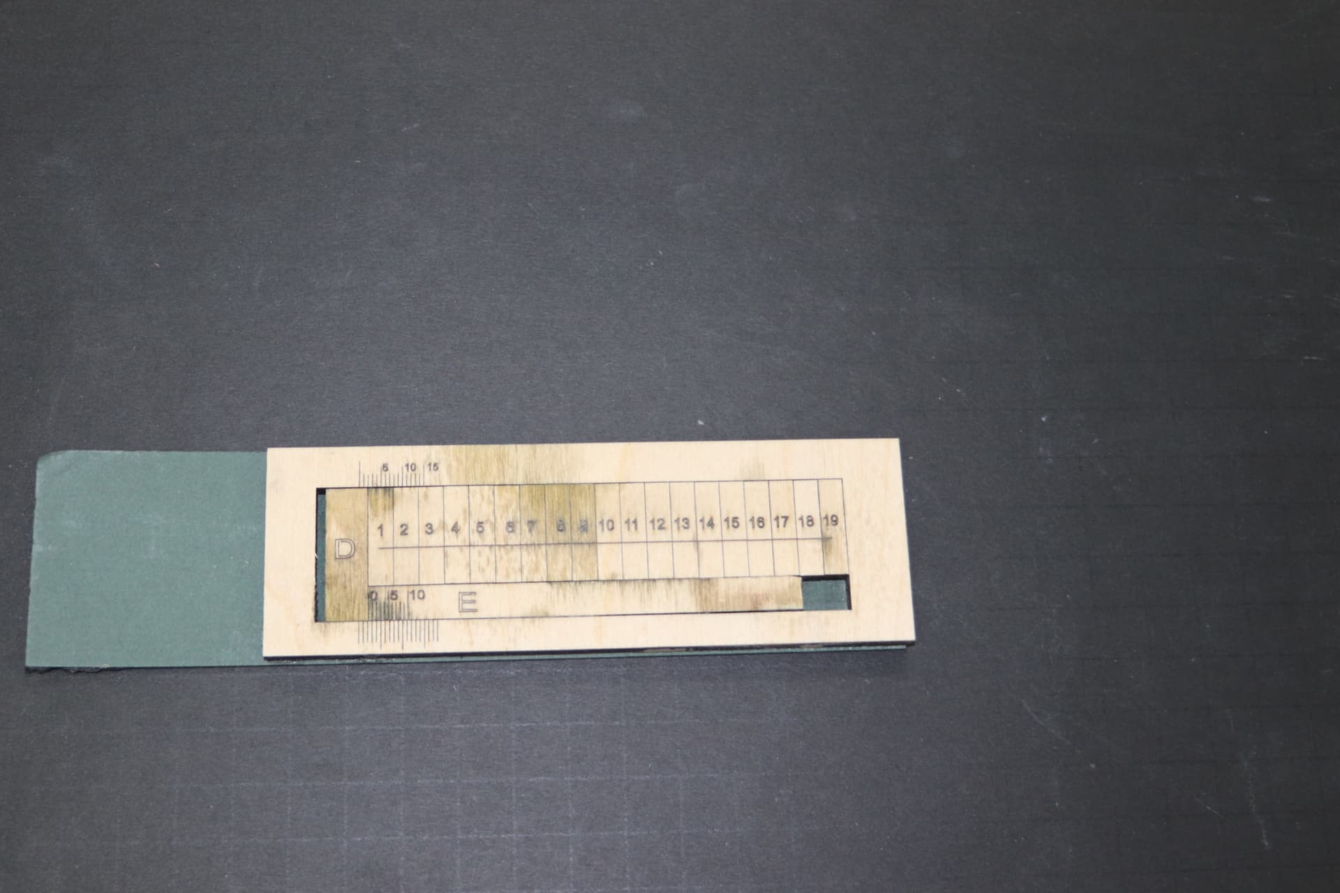
I made one with 6mm birch plywood. The vertical height was increased so the pieces don’t fall thru the grid. Was also wondering if different materials gave different results…
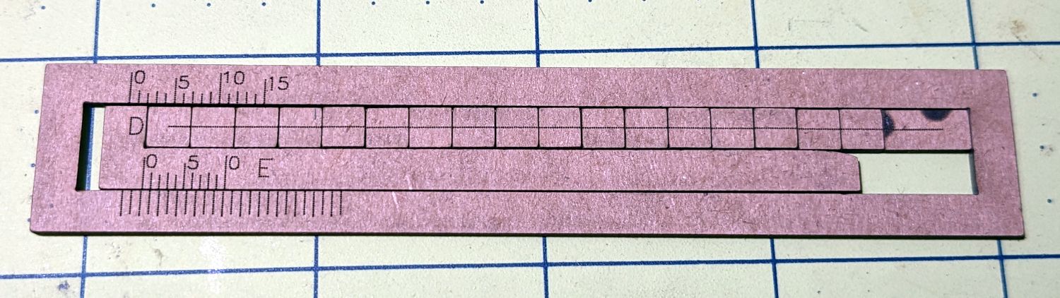
…so I used some 3 mm melamine hardboard to try another one, plus added a couple of slots to make the pieces easier to slide.
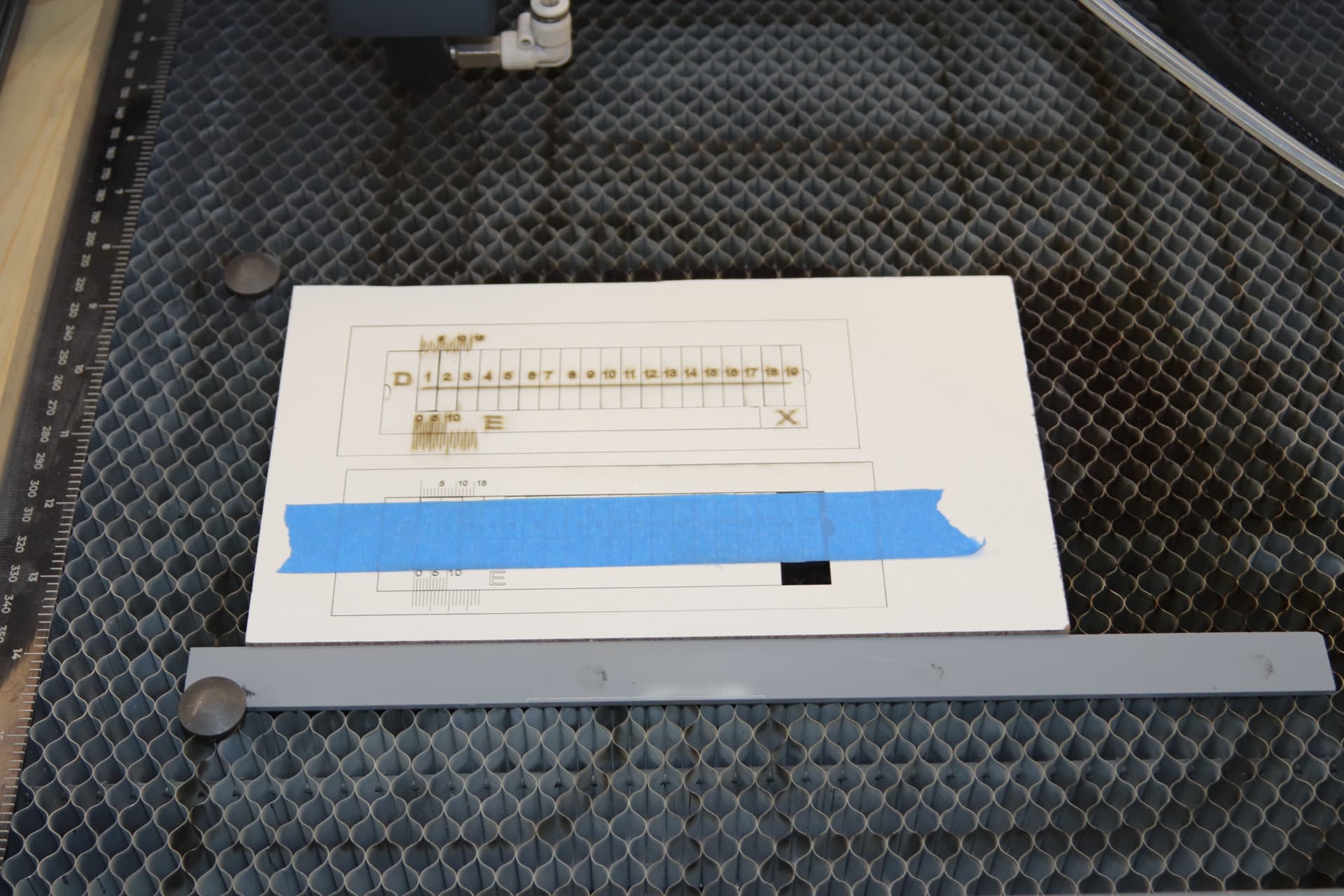
The one on the bottom covered with tape didn’t turn out so good, it wasn’t cut all the way through in places, so I burned another one.
It cleans up real nice with alcohol after laser cutting. I used painters tape to hold it together while removing from the laser and mounted it on a piece of poster board.
On both tools, the Vernier result was in agreement with caliper measurement but did show a difference between the materials which I didn’t expect.
One question though: this calculation determines the width of the laser kerf, so wouldn’t the offset to enter into Lightburn be 1/2 that amount?
Thanks again for sharing this innovation.
Yes, different materials, different settings, etc…
When we are working with such small tolerances almost everything matters.
So for every type of work where we have to take into account the thickness of the laser cut, I would do a test of these.
Thank you so much for your comprehensive review! I like the idea of taller pieces a lot, and the trick about picking it up with tape! Glad to hear you’re finding it as accurate as your digital calipers too!
Regarding halving the result, I think you’re right! Yes! Thank you! If I found my kerf was 1mm, I would need the shape to be offset outwards by 0.5mm in order for the edge of the kerf to ride the edge of my shape.
Thank you for catching that!! I’ll be sure to update my file.
I meant current revision. The file has a font that my computer doesnt have, and she has mentioned multiple times to “update her file” but there are no version/revision numbers for the file? Just trying yo do a kerf test. Thanks.
I just ignored the font issue, followed the instructions, and cut the tool out. I used the kerf calculated and my cuts seem better. If it works it works!
Just came across this file - it’s a much cleaner implementation than I had planned.
A thought I had would be to cut the tool as is to determine the kerf, then cut a kerf adjusted version (two less cuts so the spacing would change). Then for future materials and thicknesses you just cut the square pieces, and insert them into the slider and measure the kerf of the new material.
I have not delved into the world of dialing in my kerf settings yet, but it’s my understanding (at least with diodes) that the x and y kerfs could be different. If this is true, then after cutting the kerf adjusted slider, you could just rotate the squares to measure the y kerf.
In my understanding, X and Y only have different kerfs when the laser beam is rectangular or there are mechanical gaps.
In any case, the only way I remember to be able to configure the kerf for different axes would be to separate all the horizontal lines from the vertical ones, group them separately and give a certain kerf to each of the groups/layers. And this would only work well on straight lines because on curves the kerf would never work correctly.
This is exactly what the problem is about and it is not possible to find a kerfsetting that matches both x and y, it will always be an average compromise. My personal experience with kerf and diode lasers is that anything between 1 and 4 mmm material is ok, e.g. general boxes and the like. But for intarsia work I could not use my diode laser, even though it has a relatively moderately elongated beam with its 5.5W.
You have to use the right tool for the given task, that’s just the way it is.