The rectangular beam was one of the main reasons why I changed the laser head for another one with a square beam.
For projects that require more precision it makes a significant difference!
Which one is this? Didn’t know anyone made a square emitter…
Even being square, the hypotenuse distance is different from purely X and Y direction size…
If it’s not round, you end up with the same issue, don’t you?
![]()
Anything other than round is not optimal, but there is a huge difference if you have a 1:3 ratio elongated beam or a beam with 1:1 …….
This is the one with rectangular beam:
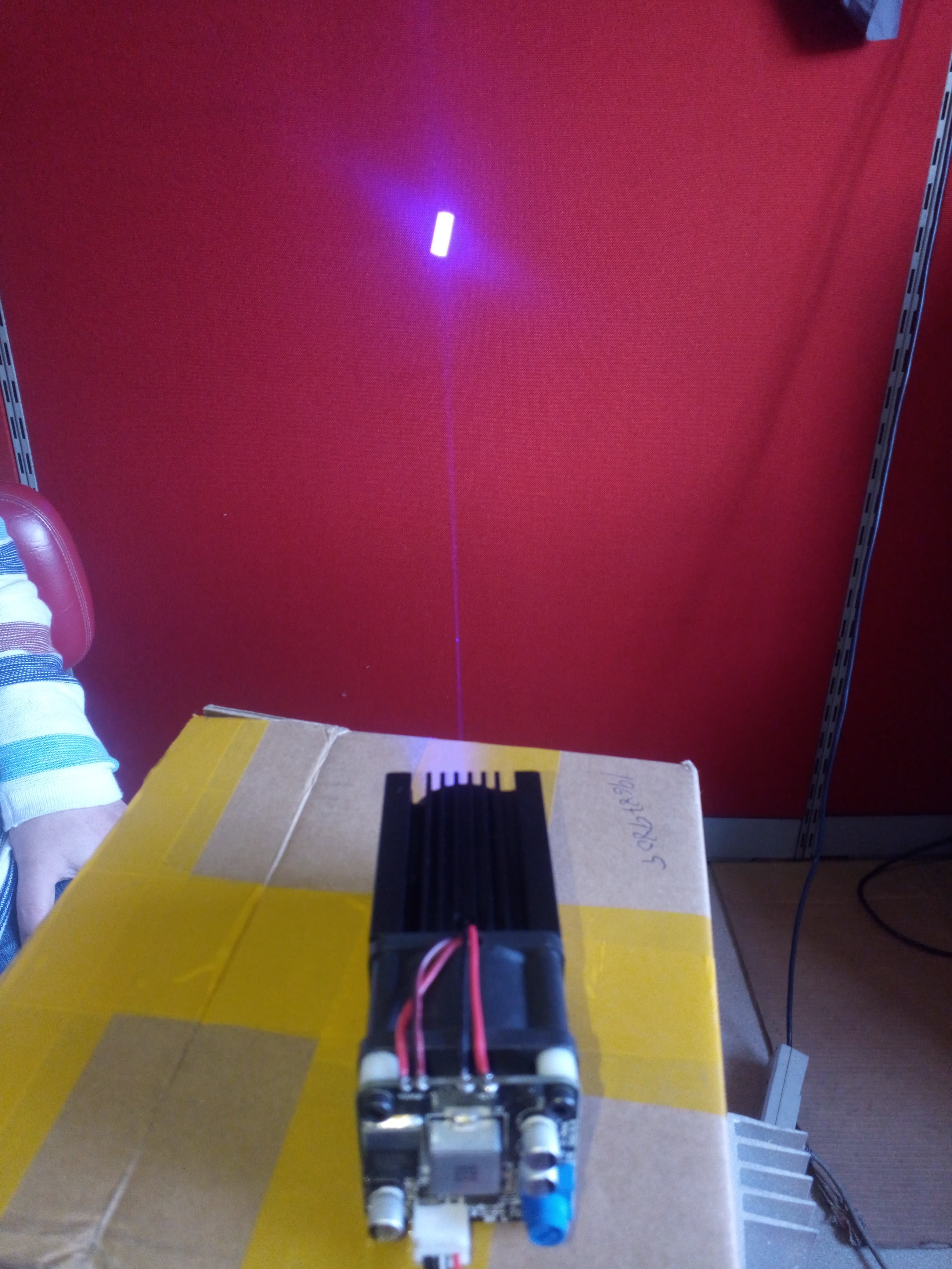
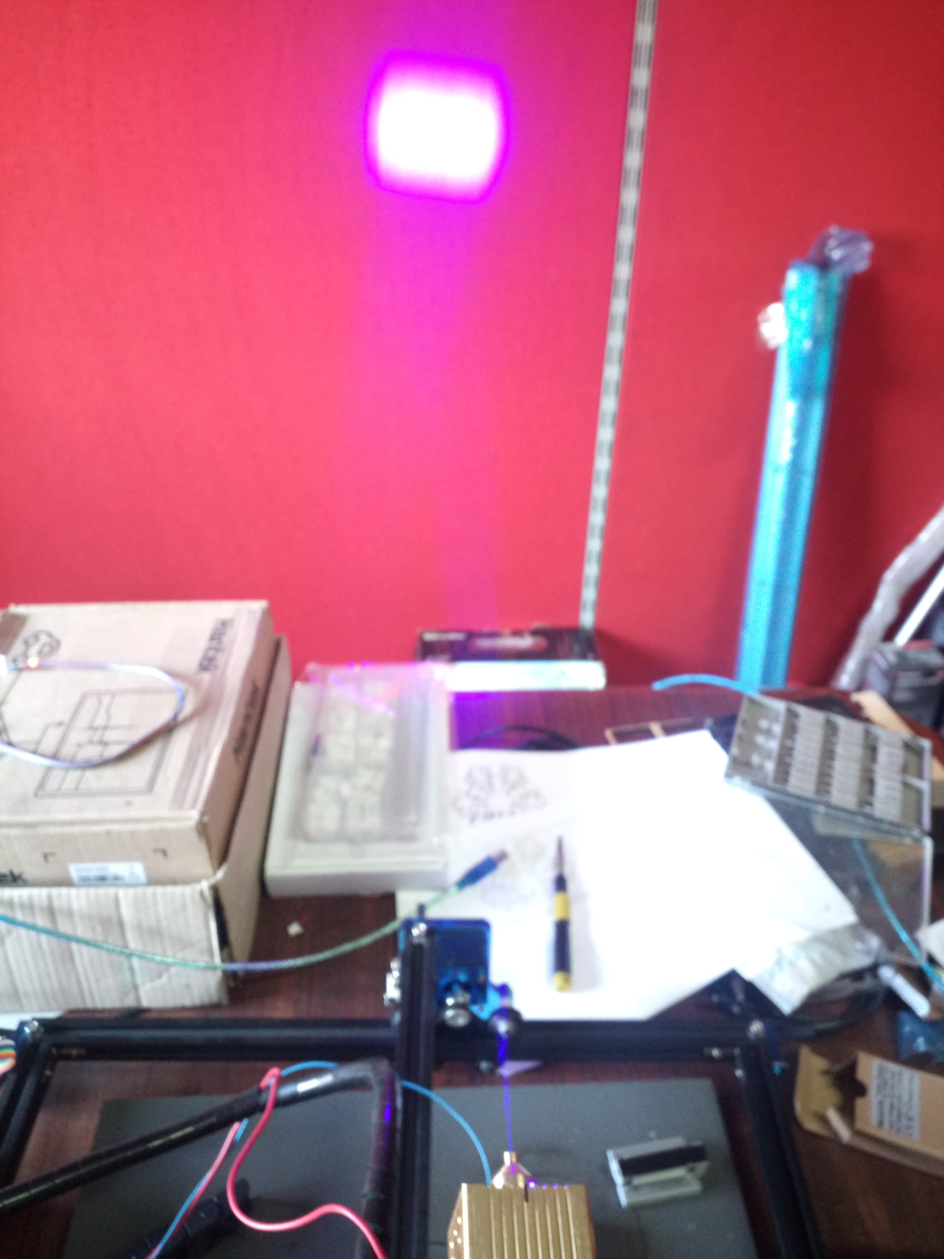
And this is a LT 40W (power consuption) fixed focus with a square beam that I am using currently:
As far as I know the construction of this one consists of two rectangular laser LEDs mounted side by side.
But I never dared to take it apart to check the veracity of the information. ![]()
Yes, of course, but as @bernd.dk mentioned:
And as far as I know, there is no round laser LED. (at least that I can buy without selling an organ) ![]()
![]()
That’s exactly it for a diode - the beam can be rectangular. I’d assumed that I would either take an average or the largest kerf as my kerf setting, but your suggestion of different kerf settings for different x and y layers while sounding complicated could be an excellent solution for slots / tabs / “dove tails” - which for most of what I’ve done is where I’d want the higher tolerances.
But, bringing it back to the topic at hand, I think that I will build a kerf corrected version of this where I can just cut out the squares in any new material to get a kerf measurement. The nature of using squares is that I can check the X and Y kerfs separately - and make an informed decision.
Again, thank you for the idea!
I apologize if I didn’t understand your intention correctly due to my poor English, but…
Why, instead of building a corrected version, don’t you simply rotate the drawing 90º, identify it as “vertical kerf” for example and run the job? ![]()
![]()
I’m looking to create a reusable tool - the “corrected” version won’t contribute to the kerf being measured, so using it with any material would be accurate. I can cut the caliper part once, and then just cut a set of squares to measure the result of a new material (or I suppose cut type). Note that I either need to increase the number of squares, or lower the denominator from 20 to 18 - as there would be two less cuts contributing to the kerf calculation…
This is square?
I believe there is a M2 value called beam quality that takes a lot of this into account.
![]()
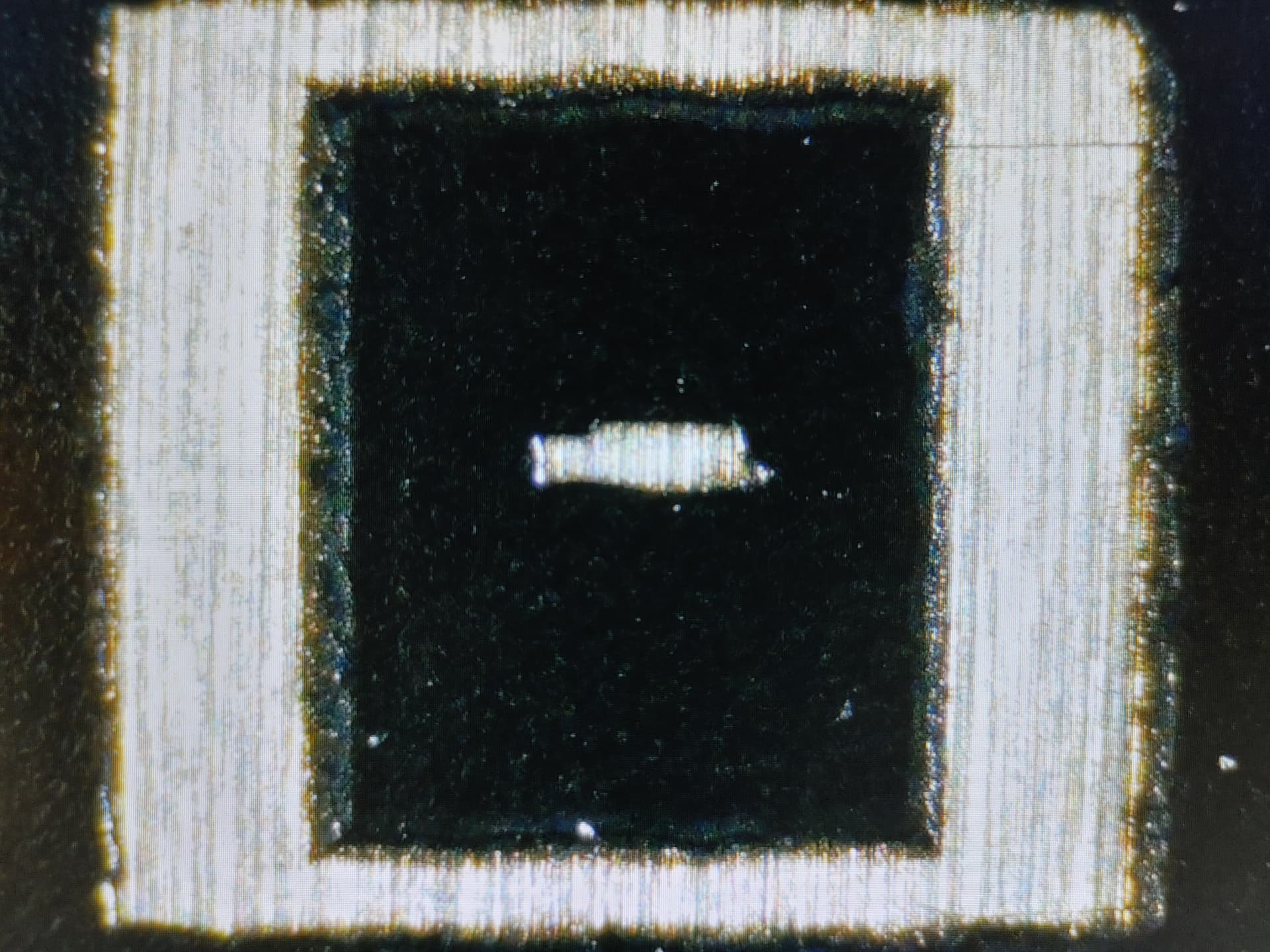
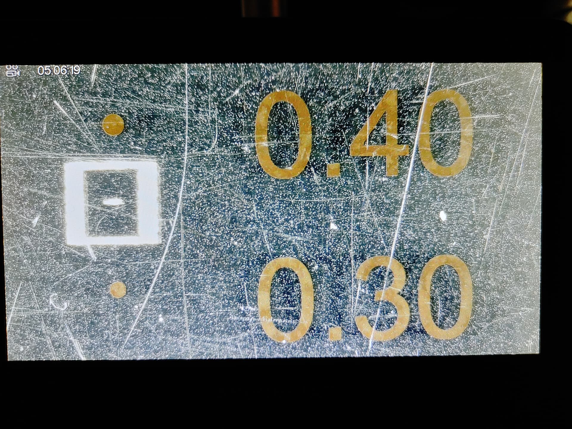
This is my 20W (quad diode) output at focus distance onto painted aluminum. 1mm square with a pulsed dot at the center. The “dot” measured approx .09mm x .40mm
2 Likes
Well, it seemed to me that I hadn’t correctly understood your intention. ![]()
![]()
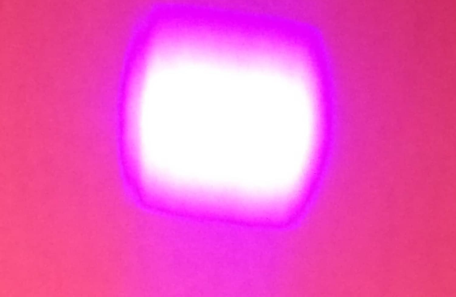
It’s a blurred square. ![]()
It is about 2m (not mm) away from the focus point. ![]()
So for me, who don’t need micrometric precision, it’s a perfect square at the focus point with the dimension (if I remember correctly) 0.02mm ![]()
Or not, because I see poorly and what is supposed to be a spot I see as a stain. ![]()
I would say this would be the result I would get if I did the same with the previous laser.
1 Like
I think General Motors calls that a “squircle”. (Reference C8 Corvette steering wheel publicity.)
Of course, in their infinite wisdom, they also decided to call the front storage compartment a “frunk”, so “squircle” probably isn’t a great term.
![]()
7 Likes
I vote that this measuring tool be added to the Laser Tools menu in LB
Upvote now.
5 Likes
Daww, you’re lovely!
If you do really want that stick it in the feature suggestions so the devs can see. ![]()
2 Likes
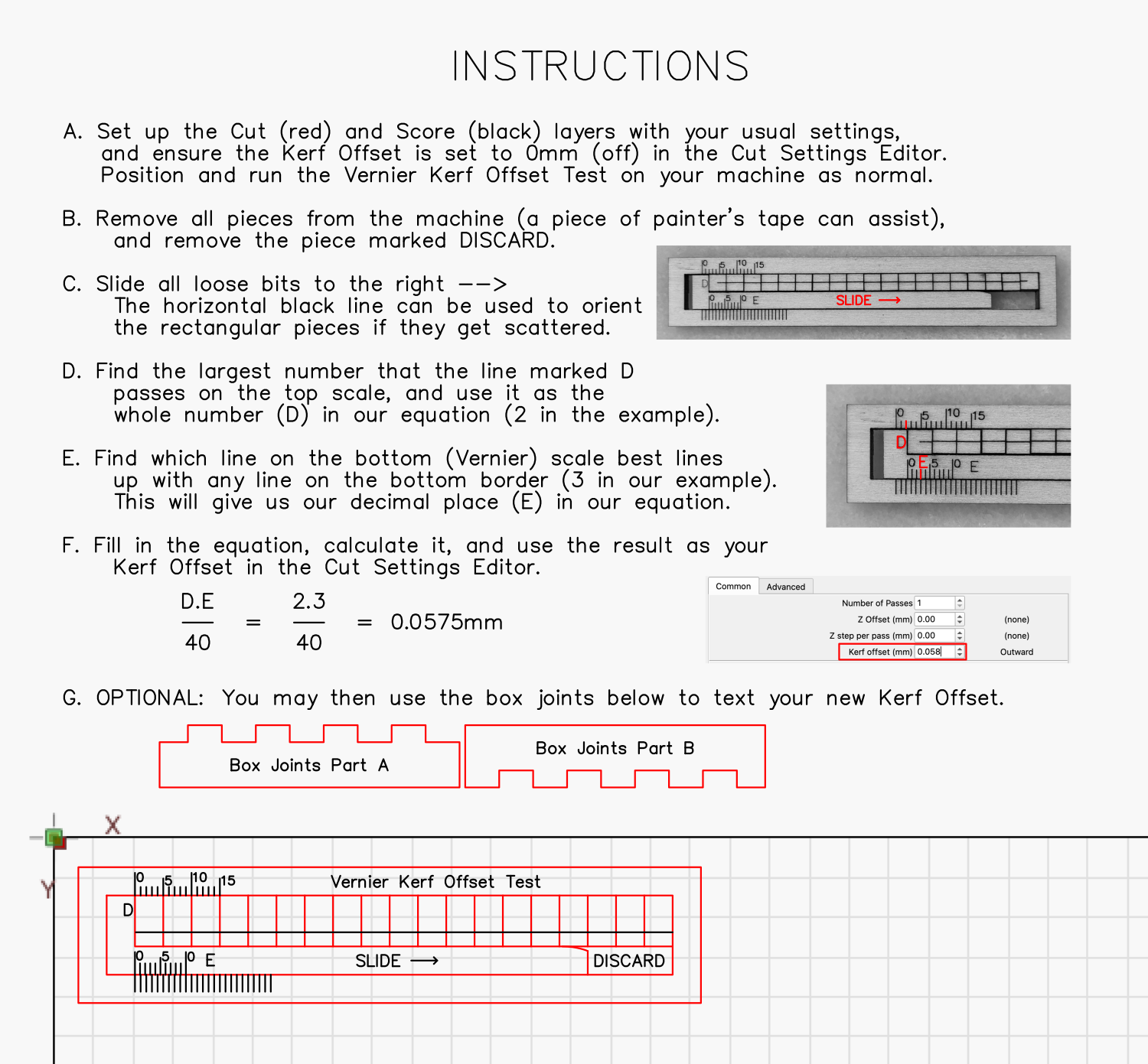
I was hoping the author of the original file could update it? There are a couple of things that need updating. Firstly, the font needs to be changed to a system font or converted to a path. Secondly, the formula needs to be updated to take into account the fact that you multiply the end results by 1/2 to get your kerf offset.
I do feel like this would be a great addition to LightBurn software, if it was updated.
If the original author isn’t able to update the file then I will do it, but I want to give the original author the opportunity to do it themselves. If they don’t respond within a week I will edit the files myself and repost as updated Kerf Offset Test w/ Built in Venier Scale.
Cam
This measures kerf, not kerf offset. Not all kerf adjustments are 1/2 the actual kerf, you might want a tight, close or loose fit.
I’d say manipulating this would be detrimental to the whole idea. IMHO ![]()
What font would you suggest?
![]()
2 Likes
Well, for the font, it doesn’t matter that much, as the writing can be “outlined” in Illustrator, for example, which turns the writing into actual paths. If I had to pick a font right off the top of my head, I would say Helvetica or Arial. I mean, if the text isn’t turned into a path, most computers would have Arial or Helvetica, probably more on the Arial side.
The original title of this thread calls it “offset” so maybe that’s a little misleading. I do however, understand that it actually measures the kerf width and it’s up to the individual to determine how the results are used.
WIthout reading the entire thread again, IIRC, there are some online calculators to simply input numbers and it calculates for you. I personally created a spreadsheet that helps me record and keep numbers based upon the material that was cut and measured since it’s different by the material (somewhat). Acrylic, plywood and solid veneers are close but definitely not the same when it comes to inlays.
Never really thought about calculating for tightness or looseness upfront from the spreadsheet. I just use the single derived number and add or subtract a little until I get the fit I’m looking for.
I may go back and see if there’s a correlation between (ultra-tight, tight, just fits, loose, or ultra-loose [for glue]) and maybe assign a percentage of the derived number. (yeah, I’m nerdy like that. lol)
3 Likes
kerf /kûrf/
noun
- A groove or notch made by a cutting tool, such as a saw or an ax.
- The width of a groove made by a cutting tool.
- A notch, channel, or slit made in any material by cutting or sawing.
You’d have to keep a list by lens length. Then by material type.
As with most of these things, the devils in the details.
Unfortunately, using natural materials we use end up with many variations that you’d have to take into account. Even the same manufacturers plywood changes by batch, which is pretty well know. Some of this is humidity, some is the basic materials used.
I have a few items I cut from 5mm sub flooring that press fit together. I’ve found a quick kerf check then make a few single cut tabs/slots for testing usually puts me where I want.
If you can figure out how to do this mathematically, that’d be great — might even make you a local hero. ![]()
Do you have a link?
![]()
2 Likes
Hello!
After the above feedback, I have created a new updated version:
You can download it here:
Kerf Test with Vernier Scale.lbrn2 (2.6 MB)
I recommend saving it to your [Art Library] after importing it.(Art Library - LightBurn Documentation)
9 Likes