Exactly…
If your kerf is 0.14mm each piece of wood will be 0.07mm smaller. 1/2 kerf from each side of the tool path.
I suggest you use 1/2 kerf if you want it to follow the tool path, since 1/2 comes off each side.
If you don’t split the kerf correctly, when you go to do a box with more than two intersecting sides, they’re not going to fit… unless the kerf is the same for each piece or you do each piece with a different kerf.
This is especially true with acrylic or materials that have no flexibility … they break.
Every type and batch of material will produce a different kerf. This is notably with natural materials and less with man made such as acrylic. Also any lens length change will change the kerf.
Finding your kerf, might give it a try with @BillieRuben tool for kerf measurement…
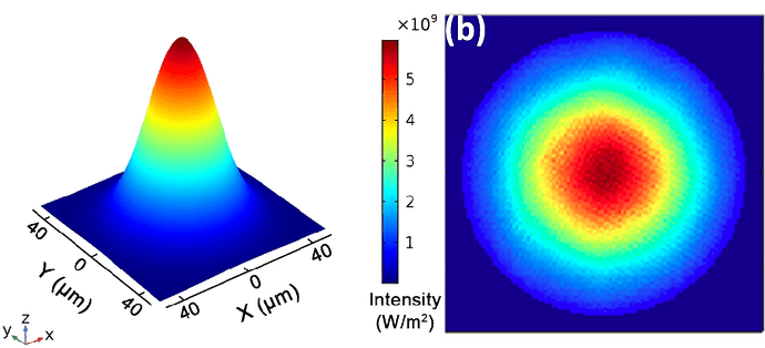
A lens transfers what it optically sees… A rectangular ssl sub-straight is rectangular and produces a rectangular output… if you make a spot you can probably see the power distribution, but you can’t if you drill a hole… We do this all the time with co2 output beam… it’s a tad larger.
The resulting beam quality or M2, I believe, relates to how closely it’s power distribution matches the perfect beam…
Rotating the scan angle in other than 90 deg multiples disables the Ruida hardware (likely all dsp types) and it must be handled by the software…
Good luck
![]()
