So I mainly engrave and/or cut where kerf is not a huge issue if at all. I don’t build or design anything with tabs or slots so I never worried about it. Decided it was time I learned and experimented with that before I give people advice anymore. Seems a simple concept. Well…apparently not for me. So, from a man I trust and is a hell of a tutor via videos, explained that the best and smallest kerf everytime is rotating the object to be burnt at 45°. Rotate your material also at 45° to minimize waste and also cutting against grain which can effect your speed/power settings and effect the kerf. I 100% agree with this. So…here is my problem and I believe I inadvertently changed Lightburn settings, or maybe need to.
I have found my kerf on my Roly Lasermatic mk 2 at 30 watts is .14mm. I can go as high as .17mm if I have a hammer and never want to get it apart again. This is fine for exterior tabs and slots. However, when I use that kerf for my tabs for interior slots, i.e., not on the edge of the project, I have to double that for a tight fit. I must have a LB setting wrong as no one else seems to have this issue with his files.
When I run a 25 mm square at a 45° angle with no kerf, then another at .14, it fits exact into the original hole. Any ideas guys? There is no problem with his files. It’s got to be a setting I somehow messed up in my end.
The beam isn’t square. It’s a rectangle. As a result, kerf is different on x than on y, different yet again for every angle between them. I have a machine with a rectangle approaching 2:1 and getting a proper joint clearance is maddening.
The fact it is rectangular is why you need to rotate job 45 degrees the get a consistant Kerf for both X and Y axis, I also will rotate my material 45 on the workbed sometimes depending on grain in material ( and it reduces wastage ).
Well, as far as I understand…and please correct me if I am way off…all laser beams are conical. The rectangular is optical focus…not optical density…I think. So it’s really elliptical, but manufacturers use optical focus, where laser users need optical density. As far as I know or understand no beam is rectangular…can’t be. It’s an average.
But that isn’t really my problem. Using a 45° rotation of objects will give the best ‘average’ I guess? But why would I have to use twice that for tabs to fit interior slots? Now if I made a simple fitting ‘side’ tabs and slots, I would use a .14mm instead of .28mm. I guess I am just stupid. It doesn’t make sense to me. Why I thought I must have messed up a LB setting somewhere.
As Steve replied to me earlier, and explained in an email, that would effect material thickness. It wouldn’t work. I am really confused why outside tabs and slots work at my nominal thickness of 3mm with a .14 kerf, yet I need to double that for the tabs to fit in interior slots. I am sure it must be some setting I unintentionally changed in Lightburn somewhere somehow.
This was done at a ridiculous .27mm kerf. I know I somehow screwed up some setting. I am using a Roly MK2 30 watt. I normally have to use a .14 kerf for outside tabs and slots. It doesn’t work for my interior slots. I resized all slots to 3mm. Close enough for 2.96 thickness of the wood.
I am not plagued by an elongated focus with my CO2 laser and also do not need to compensate for it with placing material in 45 degrees …
But working with Kerfsetting is a regular part of my daily work, so much that I don’t really think about it anymore. For new materials and once in a while, however, I do a Kerf test, generated from this site.
One of the most frequent problems with Kerf Setting is that Shapes is not closed. If my “Standart, +/-” Kerf Settings does not give the desired result, I know I have to look for non-closed Shapes.
I don’t understand this. Not being being a jerk, but that doesn’t make sense to me. All Enlogated focus, short focus, whatever. Kerf is kerf. It is the material cut away from the initial line. Be it with a laser, miter saw, table saw, et al.It doesn’t matter what cuts it, there is material that is lost. Cut any 5" or 5mm board in half…you will not get 2 pieces exactly 2.5 inch or 2.5mm. That simple.
It is not that I don’t understand kerf, it is rather that what I do to compensate doesn’t make sense to me. That a tab an exterior tab is less kerf (in my case .14mm) than a tab that fits an interior slot at double that.
I am sure I have a setting wrong somewhere. Otherwise I am lost. It does not make sense to me. It’s why I am asking in LB forums
While it is possible to produce a lens system or to otherwise manipulate the beam to produce more rectangularish optical density spot, something like that is extremely expensive to pull off.
Not to mention utterly unnecessary in all but a few special applications.
The only application where rectangular density would be immediately beneficial, would be miniature QR code marking.
There may well be others as well, but I for one can’t think of any.
As a matter of a fact, a rectangular spot would obviously not produce uniform kerf on other than on the directions of the sides of the said spot.
And those sides wouldn’t necessarily be the X & Y of the work area.
True as well, on both counts.
Checking the density pattern shape is really easy, mark or burn a single dot or “drill” a beam sized hole, and look at it on a microscope.
Projecting the pattern on the wall etc. 10~100 times of the focal length of the optical system does not produce accurate representation of the actual beam/spot in -or near- the focus point, for reasons that anyone with even a rudimentary understanding of (cheap) optics should be able to understand.
All laser lenses focus the the light conically as far as I am aware. It’s physics. Regardless of lens, regardless of “right” or “wrong” positioning of the focal lens. Different focal density when comparing CO2 and Diodes…but same really.The difference is not what I’m asking.
I’m having the problem of kerf. So I’ll end this convo here. I just think I have settings wrong. No one else…100’s if not 1000’s of people do not have this issue with the files. So was just asking if I messed up default settings somehow in LB.
Thanks guys, I appreciate all reponses. Sorry it went off track.
Brad
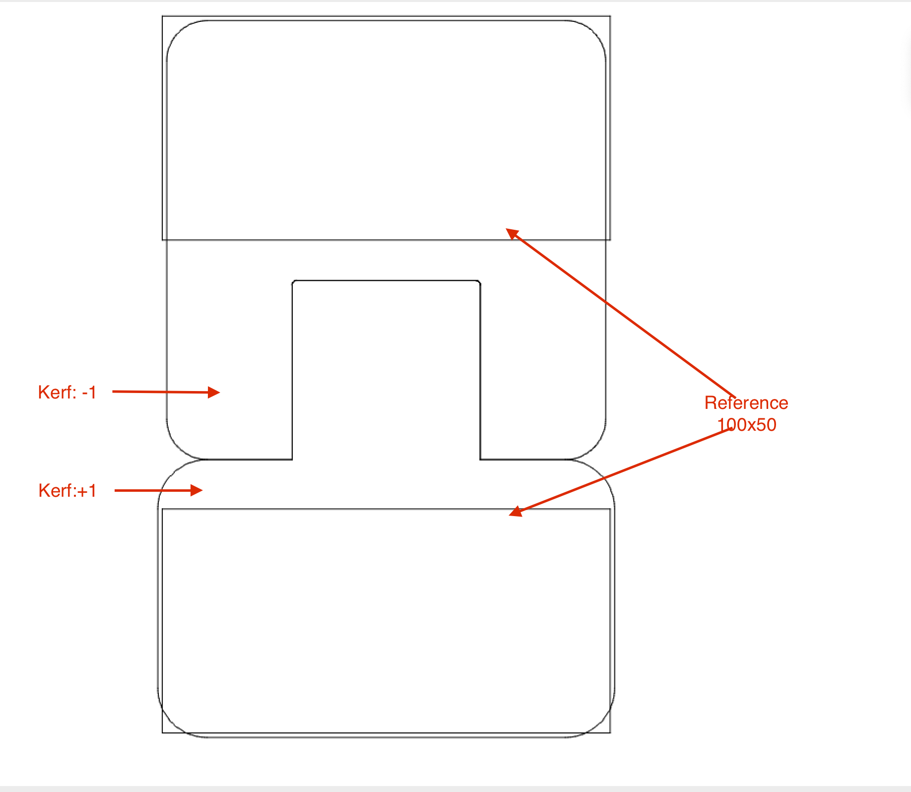
Regarding your specific problem… Are your adjustments all done using the kerf offset parameter? If so, it may be worth testing using a zero kerf offset and substitute by offsetting the cut vector itself. This way you can be absolutely certain the offset direction is as-intended.
Personally, I don’t care for the kerf offset function. I prefer to use shape offset or otherwise design the kerf into the vectors.
Correct if we are talking about focusing incoherent light, which these lenses are designed to do, but a Laser beam is coherent light and we are trying to focus intensty of the beam not the optics, resulting in a roughly rectangular shape, try and imagine it as two different blades, one for X and one for Y, the X being narrower when traveling in the x direction and the Y being wider traveling in the Y direction which is why you can get two different kerfs as the cuts are different widths travelling in the different direction.
If your kerf is 0.14mm each piece of wood will be 0.07mm smaller. 1/2 kerf from each side of the tool path.
I suggest you use 1/2 kerf if you want it to follow the tool path, since 1/2 comes off each side.
If you don’t split the kerf correctly, when you go to do a box with more than two intersecting sides, they’re not going to fit… unless the kerf is the same for each piece or you do each piece with a different kerf.
This is especially true with acrylic or materials that have no flexibility … they break.
Every type and batch of material will produce a different kerf. This is notably with natural materials and less with man made such as acrylic. Also any lens length change will change the kerf.
Finding your kerf, might give it a try with @BillieRuben tool for kerf measurement…
A lens transfers what it optically sees… A rectangular ssl sub-straight is rectangular and produces a rectangular output… if you make a spot you can probably see the power distribution, but you can’t if you drill a hole… We do this all the time with co2 output beam… it’s a tad larger.
The resulting beam quality or M2, I believe, relates to how closely it’s power distribution matches the perfect beam…
Chris, yes. I am using the adjustments for kerf in the LB settings. I understand what you are saying though but regardless of using an offset in design, or using the kerf offset, it is exactly the same coding being used for the function. For any interior slot…say a 2" rectangle with 3 slots in the middle, I need to double my positive kerf from .14 to .28 for the tabs to fit correctly. On Exterior slots and tabs, say a box joint, .28 is way too huge (like what one would expect) by 2x. It needs to be the .14.
I mean I can make it work, but I am still convinced I screwed up some setting somewhere, sometime as this makes no sense to me. More complicated designs will use both interior and exterior tabs and slots, and this I cannot easily compensate for. I know I am probably not explaining this right, or I am missing a simple concept and will hopefully have a “god what an idiot I am” moment.
I believe he means using a negative kerf for slots, and a positive kerf for tabs, or vice versa. But because the kerf would be unifomally applied to the slots, it would effect the material thickness. So width for a slot is your material thickness. Changing that would not work, it would be worse really.
As I said before, I am probably just not explaining this correctly. Thanks for everyone’s replies. I appreciate all of them.
In my example, +/- kerf, the settings cancel each other, but the shapes themselves change in their size. It makes no sense.
The Kerf Tool is intended to compensate evenly for a very small value and should be used on both Shapes to achieve this effect.
(If you come from the metal industry and think about Press Fittings for eg Ball Bearing then it is something completely different. Here you have a specific measurement of your bearing and need to customize the shaft, only the shaft.)
Anybody test all these square-rectangular-conical-power distribution- whatever theories? I did a while back…
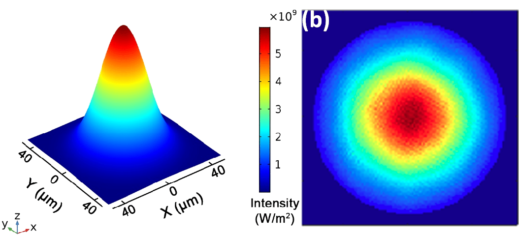
While testing a suspicious weak output 5w laser, I hooked it to 12vdc. When I pushed the test button and pointed it at a wall about 6 feet away, I got a rectangle about 4-5 inches long. It appeared to be equally bright over the entire surface, including the corners.
Any variance in the power distribution would not be in the laser. The entire lit area would receive equal power.
What WOULD happen is the heat density distribution in the material would not be equal. All materials are heat conductors to some degree. We know metals conduct heat. Wood also does this, to a lesser degree. Otherwise, houses would not need insulation and big heaters or A/C units.
That said, what will happen is the heat in a corner will be conducted away faster because you have two edges compared to one edge along a side.
No, I am no an engineer, but I am a Geek. That is almost as good, right?