…I’m not an engineer either (although I’ve gone to distance learning with Russ ![]() ), but my 5.5Watt diode laser creates an elongated square when optimally focused. approx. 20 to 30% more elongated in relation to the width or vice versa, ascertained without a microscope. It is the logical consequence of the laser diodes that were used this time, how it is today and how or whether it is compensated for in laser machines with more diodes, I do not know, but it could be possible.
), but my 5.5Watt diode laser creates an elongated square when optimally focused. approx. 20 to 30% more elongated in relation to the width or vice versa, ascertained without a microscope. It is the logical consequence of the laser diodes that were used this time, how it is today and how or whether it is compensated for in laser machines with more diodes, I do not know, but it could be possible.
1 Like
This is called a rectangle.
I would hope they orientate the second (20w) and fourth (40w) diodes at right angles to the others. That would give you a cross pattern, but be much closer to a circle. If these higher units claim less than a 0.08mm dot, assuming perfect collimated light beams, they may be wishful thinking. In fact, I wonder if you can have two coherent light beams in the same space without interference patterns. Sorry for the Geek Talk.
Thanks for the info, I think it got lost in translation ![]()
I know we’re veering slightly out of focus here, but I find this interesting and it informs the general topic of kerf as it relates to diode machines.
I haven’t actually checked the output of this machine in a while. It seems my beam geometry has degraded even further. What used to be a disappointing ~2:1 rectangle is now closer to a truly dismal ~4:1
So, here’s the setup. I started with five 1x1mm squares on five layers, each stepping 1mm from factory specified focus.

I thought I could draw a .001mm square inside each to approximate a point, but LB wouldn’t output anything until like .005 and that ended up being a bit distorted by machine flex/wobble/backlash, so I just did a single 1.5mm square and then pulsed the laser manually at the center.
These are the results thru my scope with a crack ruler overlayed for size and shape reference. The material is coated aluminum. The laser is a quad diode with a supposed 24W output and a supposed spot size of .08 x .06. I work in a metrology lab and checked my crack ruler on a calibrated optical mic that cost more than a new car. The dots I’m using here are approx .02mm oversize, so the .4mm dot is actually about .42 (.4215 to be precise)
The label text is 1mm SHX font. ISO9, I think. If it matters.

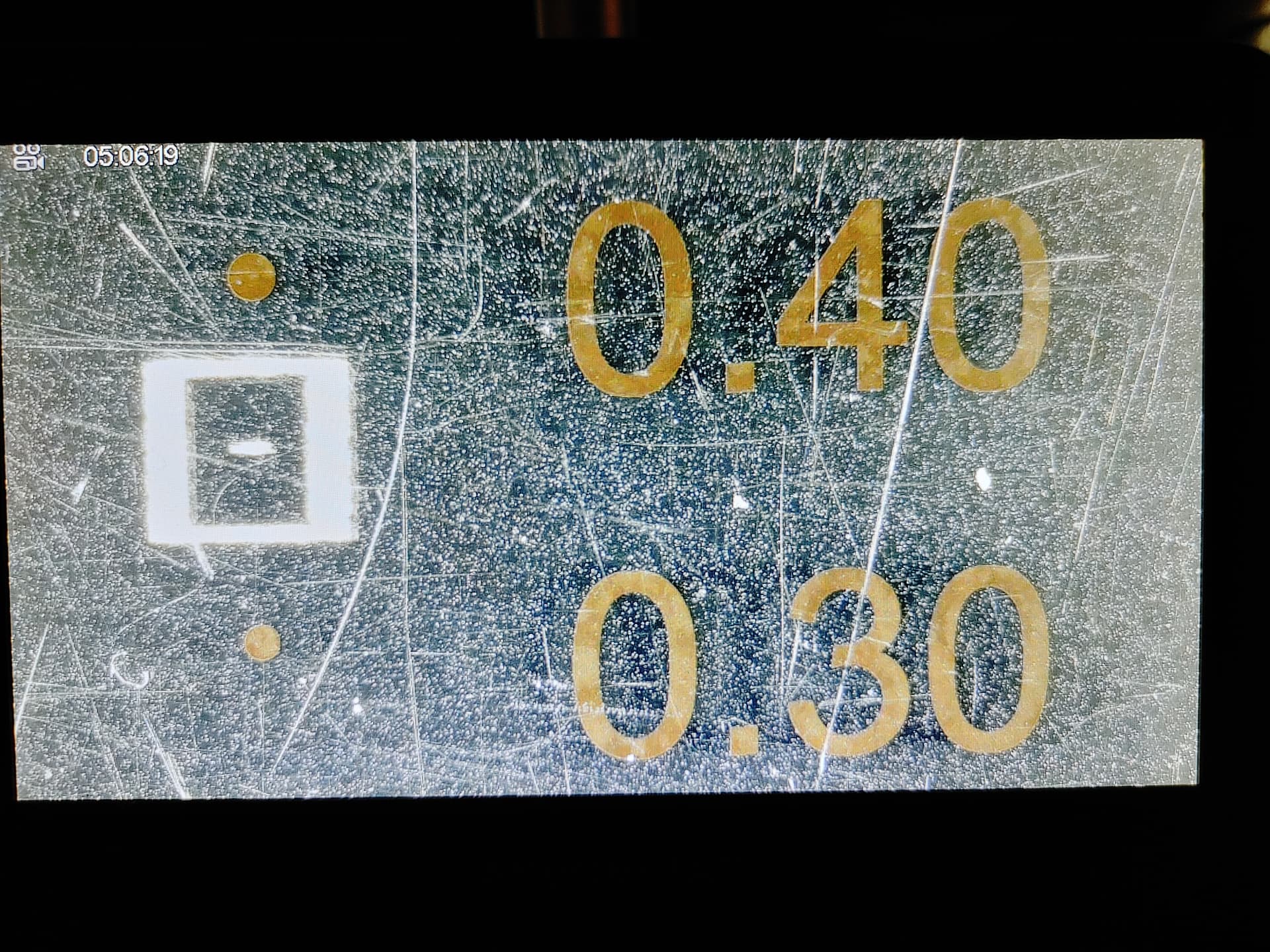
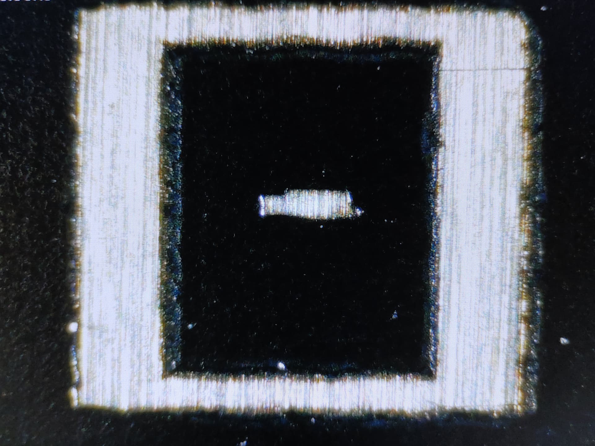
A bit closer. Circle? Ellipse? Square? Rectangle? You be the judge. Remember the “square” is just a frame to help me find the actual spot under the scope. The spot itself was a manual pulse, so there is ZERO axis motion (other than some very slight potential vibration from the cooling fans or other environmental “noise”)

I apologize for the image quality. It’s a pain to dump the pics from the digital scope to my phone or PC, so these are just pics of the scope display. Good enough for conversation, I think.
4 Likes
Hi.
More than good enough for conversation, so thank You @cggorman for taking the time to do those extremely informative tests.
I’m truly amazed with the crisp sharp corners, and the spot would most likely be rather perfect 1:4 rectangle without the environmental noise/disturbance You mentioned.
I do agree that the 1:4 itself is pretty dismal for fine detail engraving/marking or intricate cutting -not to mention kerf compensation- but if taken into account in the designing phase, can be compensated to a degree.
Is the head still under warranty by any chance?
If things like that fall under the warranty, that is.
In any case, those results are pretty much as far from mine as can be.
I do not have an access to a digital microscope, so I unfortunately don’t have any pics to prove it, but I’m slooowly working on it ![]() .
.
That’s not very high on my priority list either, so it might take some time.
On my xTool D1 Pro (purchased ~17 months ago), the 20W 455nm produces an oval (onto wood), and the 2W 1064nm produces a round dot (onto an aluminium offset sheet backside).
I don’t have a way to accurately measure the spot, but I’d say that the spot dimensions xTool advertize are optimistic at best.
Roughly ~20% bigger than advertized I’d say.
Doesn’t matter much with the 20W, but with the (near)IR head obviously loses power pretty fast when the already finicky focus point shifts and the spot diameter increases rapidly.
Thanks again @cggorman for the tests, even though because of personal experience I’m still not quite ready to believe that all lower budget diode lasers are (/were) capable of that ![]() .
.
Very good to know that some actually do though, should the need arise.
That said, I’d probably still take round diode spot over a rectangle or oval if given the chance.
Regards,
Sam
![]()
Nice documentation ![]() . Your displayed result is what can be used to determine how one’s diode laser can best be used in relation to tolerances and cutting ability.
. Your displayed result is what can be used to determine how one’s diode laser can best be used in relation to tolerances and cutting ability.
In order to measure/see the difference between the 2 different “spot lengths”,without an expensive microscope, it will be possible by designing a test with a filled square, where the line distance is set so that a distance is just visible with a normal magnifying lens. Then rotate this design to show the min-max deviations, ie. if the elongated spot is at 0 degrees, turn the design 90 degrees in LightBurn and start the test again. It is somewhat theoretical because the diode direction is rarely at a 90 degree angle to the nozzle head mounted. But you can clearly see the difference, especially when we talk about 1:4 ratio deviation.
Regarding warranty… I am not satisfied with the beam quality of this module, but I question whether Ikier/Atomstack would consider it bad enough to replace and I have even greater doubts that any replacement would be enough better to warrant to effort involved in getting one. I’m staying with the “devil I know”. If I start building more heavy items or things requiring precision fit, I’ll just get a nicer machine.
Same part, but I zoomed the scope in a little closer and tried to get a nicer photo.
1 Like
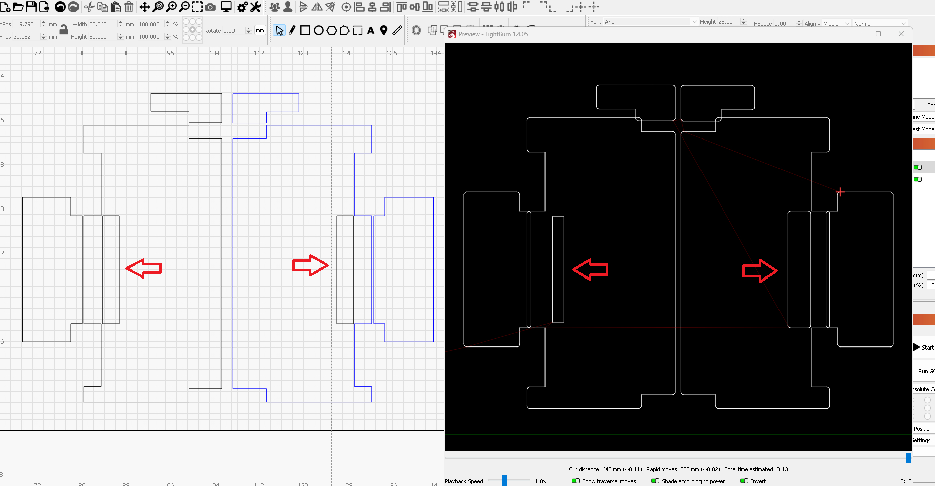
Brad, I did some playing around with the kerf offset tool and I may have found a culprit for your issue. Is there any chance your interior slots are on a different layer than the outer profile?
These are mirrored shape-sets with both inside and outside profiles. The left set is all one layer. The right set is two layers. Both layers have the same settings, but the set with two layers doesn’t properly recognize “inside” shapes… I exaggerated the kerf offset to help see the changes.
Also notice the corner radii automatically applied by the tool.

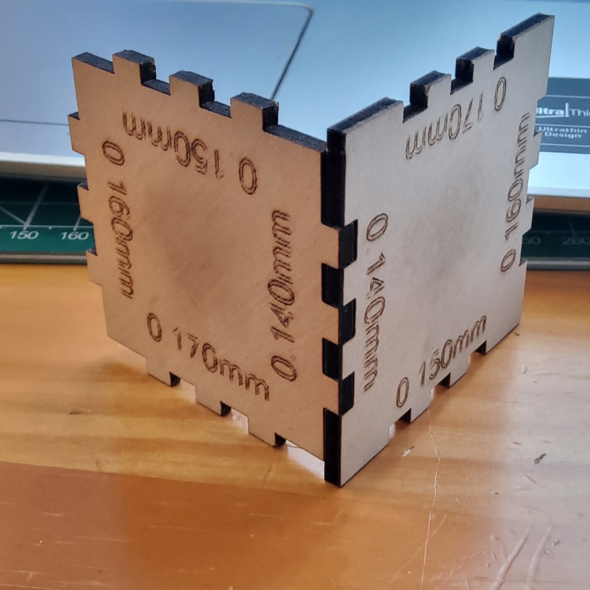
Chris, Thanks. This is something I will look into more. So I am using 3mm material and the design I am using has a hexagonal base, with the slots set in 1.5mm from the edge of the base to the middle of slots so when the panels snap into them, the panels are flush to each other all the way around and to the base itself. This is why I refered to them as interior slots. So yes, I am using 2 layers. One for all the slots with no kerf or offset applied and one for everything else with .28 kerf. So, for example, the base will have the slots on a layer with no kerf and the outside cut with the kerf applied. I did this since then panels with tabs will have the kerf applied to the whole piece.
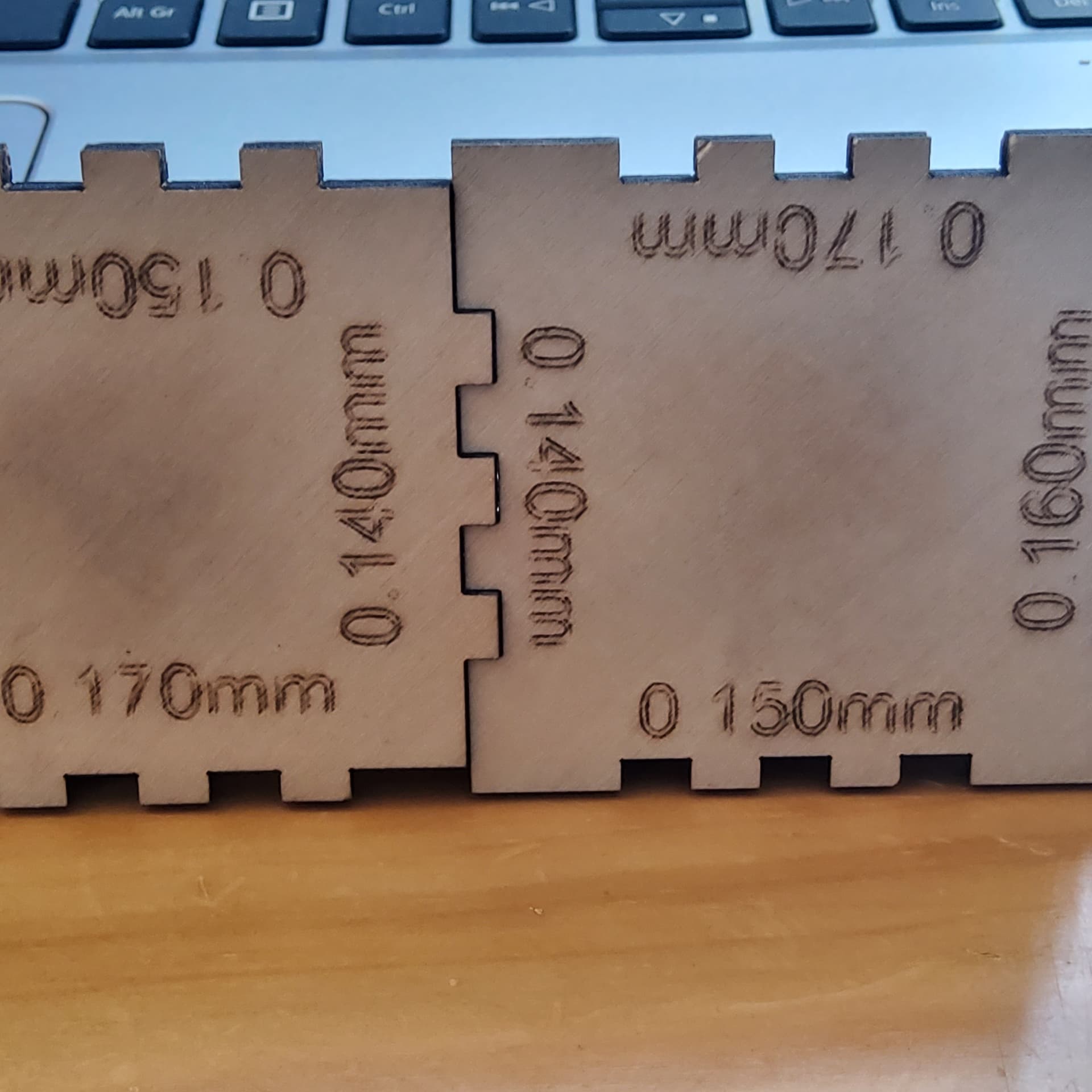
When I do the finger joints, say for boxes, I only need to add 1/2 my kerf (.14) which is to be expected…all one layer. However, if I make piece, a rectangle with 3 slots in the middle, the exact same piece with tabs on the exterior and only use kerf on the piece with tabs, I need to use .28 kerf. I don’t have email set up on my computer I use for Lightburn so I can only take an actual picture of the screen and post if that would make more sense. I have no idea why this is the case or why the hundreds if not 1000’s of people that use this guys files never encountered this issue. It is definetly not his fault and the files are correct. Something in my Lightburn must be off somewhere.
I’m sure it would be helpful to all if we could see the problem. However, I’m most definitely sensitive to people not wanting to share certain files. I certainly don’t share much in the way of project pictures, let alone files. If this is the case, maybe build a simple functionally representative subtitute using your methodology and copy the files to thumb drive or phone and upload from the destination device.
I can share enough so you can see what I am doing. It’s not my file, so I can’t share the entire thing, however boxes.py or gravini will let you d/l a hexagonal box that is pretty much the same design.
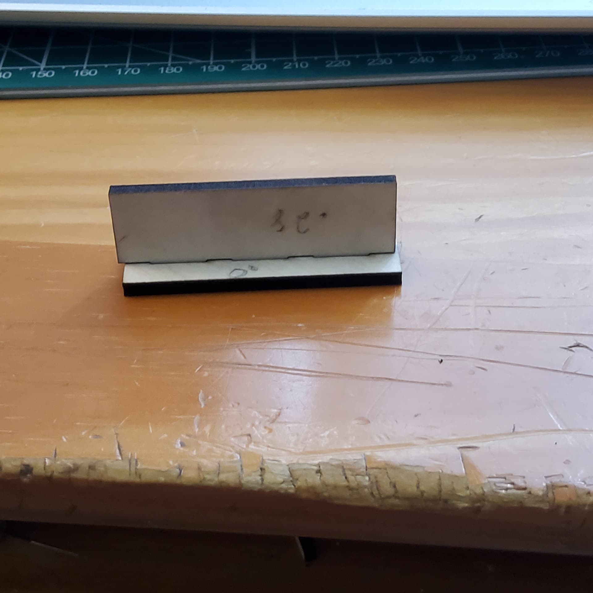
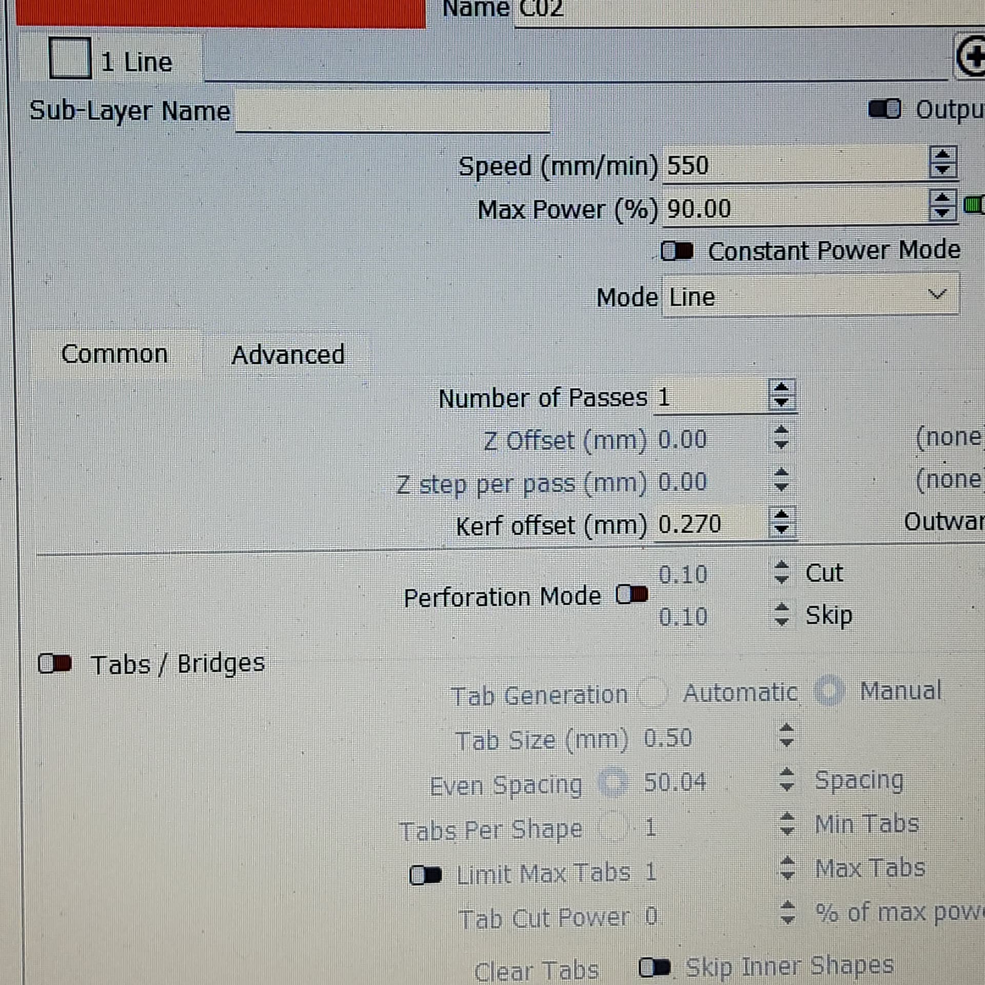
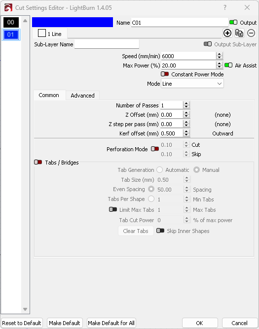
The first set of pics is my kerf for the finger joints. .14 kerf. The second set is my simple test of slots in the middle of the first piece cut with no kerf and the second piece cut with tabs and .28 kerf. The rest is the LB of the design and settings.