X's and Y's and Offsets, oh my!

So I have a question regarding steps/unit and kerf offset.

Up until now I’ve not needed to be concerned about fitting items together and dealing with kerf offset.
So performing a couple of different types of kerf tests to determine what the value is, I’m getting stumped on what’s going on.

I did a 1" square with no offset as prescribed in the tests, but in the X I’m getting a measured average of 1.0004" and in the Y I’m getting 0.9965".
Since I’m so close in the X, it got me to thinking about the step/unit and how it plays out with the end results. From my perspective, if you dial in the step/unit to get it to cut exactly to that dimension, i.e., one inch, without accounting for kerf offset, then in reality the steps/unit could be off. Miniscule probably, but still off.

Now with my background in CNC machinery, where the bit size can be also be offset by half the diameter of the bit, it cuts exactly that from the drawn or coded line. The difference in determining steps/unit in that arena is that you don’t have an unknown nor does it matter to do the determination. What I’ve done in that setup is to simply set up 1-2-3 or 2-4-6 blocks, give the machine a distance to travel that matches one of those sides and check/verify the actual distance moved and recalculate the steps/unit accordingly. Easy peasy.

However, since I don’t know what the actual kerf offset is in the laser arena, it seems logical to me that this will be many trial and error permutations to get it right.

If I draw a line and tell LightBurn to move that distance from end to end, I’m guessing I could also set up the same blocks and measure off the side of the laser mount with a dial indicator as on the other CNC machine. Check and adjust, since I’m not attributing any laser offset, just purely movement.
Then I could do a cut and measure accordingly. Now comes the fun part, X & Y of the laser beam isn’t a perfect square AND LightBurn doesn’t allow for the different axes, only a one-size-fits-all kerf offset.

Have patience with me as I’m sort of OCD when it comes to stuff like this.
I do have a 24" dial caliper that I do measuring with so that’s not a problem to check the end result of “expected movement + kerf offset” to determine the actual offset. Seems that would be best to do on the longest line I can do with my laser bed setup.

  1. Stack all of my 1-2-3 and 2-4-6 blocks end for end
  2. Measure that amount
  3. Draw a matching line distance in LightBurn
  4. Have the Laser Mount move that amount via LightBurn
  5. Measure actual end result
  6. Set steps/unit as needed to get the movement as close as possible to the expected
  7. Do same for other axis

Then I think I could get a more realistic number for what the kerf offset equates to once I know for certain the head is moving accurately.

Am I way off in left field here? Is it really necessary to go to that much trouble? Sure I can play around with the kerf offset by trial and error but that won’t get me to an accurate part along with an accurate fit.

It’s a bit of a confusing read, it seems like you’re complicating it more than necessary.
You have different machines and I will deal with “normal” diode or co2 systems, I don’t know anything about milling machines with connected diode lasers.
With both of the first mentioned machines, I draw and engrave the largest possible square and then try to measure it as accurately as possible. In machine setup, I then adjust, if necessary, steps for X and Y. Then I check this correction.
Kerf is uninteresting to me during the whole process, it has nothing to do with steps.
When you cut out a test piece 50x50, it must measure 50x50.
Of course, it is important that the focus is perfect for this operation, otherwise you will get incorrect measurements later.
Kerf must be taken into account during the construction of items, but not to adjust your machine’s measuring system, nor do you change the steps of your milling machine when you change from one type of cutter to another.

Sorry that I was unclear.
I completely understand they are different machines but they do both work with stepper motors and the linear movement is calibrated based on steps/unit.
Yes, kerf offset has no part in steps/unit. Understand that as well.
To simplify, I think I need to get the steps/unit dialed in first with no regards to kerf. Just simply measuring linear movement.
Once I’m certain that the steps/unit are spot on (or as close as I believe I need), then I would do a large cut and measure the result. For example, if I said travel 23" and its doing just that, then I’d cut a line 23" and measure the difference. Seems that would be the actual offset coming into play then. Yes?

Of course! :grin:

Do not drag the kerf width into the axis calibration fight, because they are not related.

Opinion: folks who tell you to calibrate the axis based on cutting any material do not know what they’re doing. Engraving vector lines is OK, but it’s even easier than that.

Instead of wringing your blocks, deploy the longest bestest engraved metal scale from your armory:

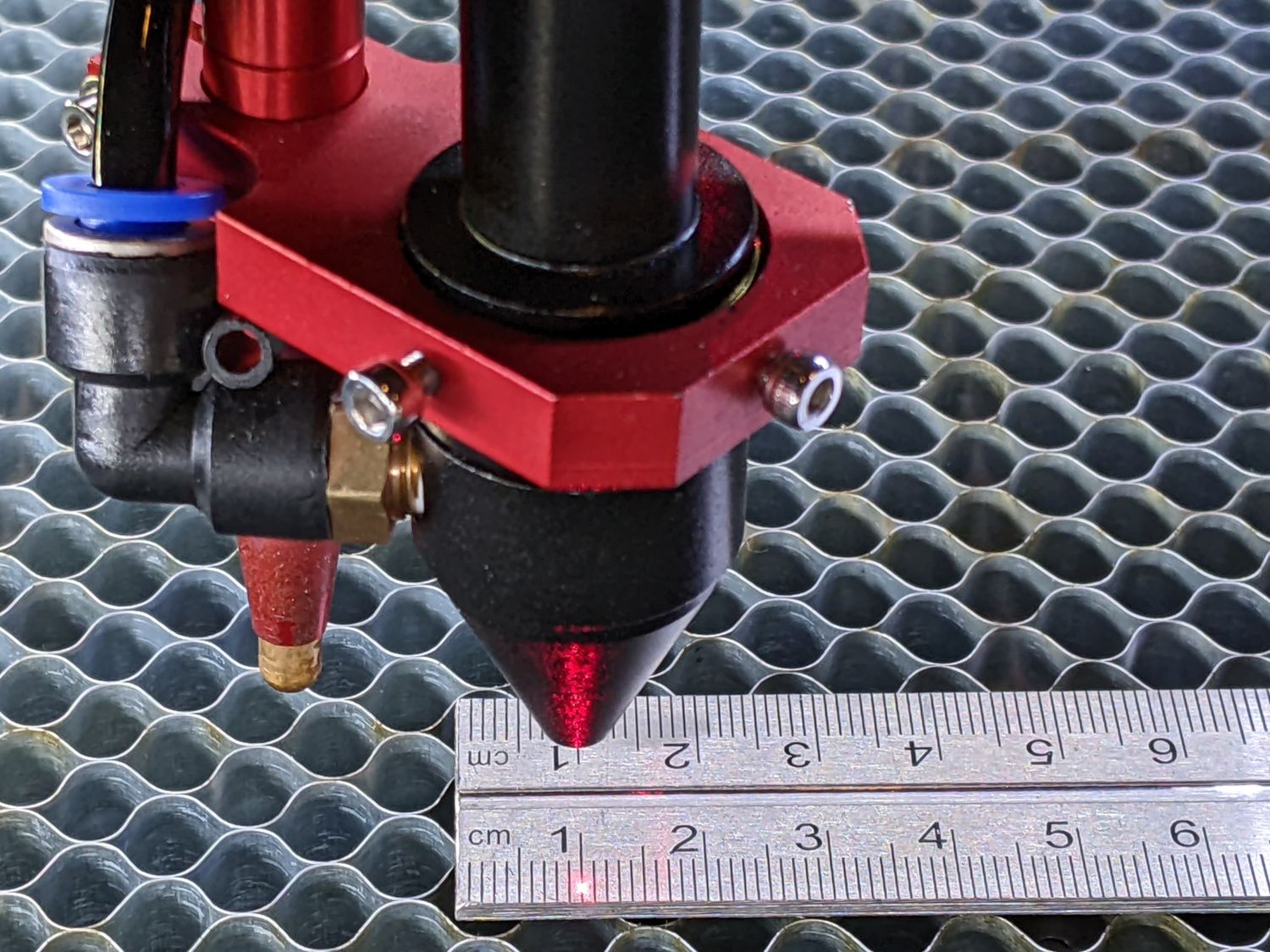
Align the scale parallel to the axis, align the laser (with its red dot pointer or test pulses) at a convenient division, jog a known amount, and see if the beam is dead on where it should be. If not, tweak as needed.

In principle, the step/mm (mm/step or µm/step for Ruida controllers) is not amenable to tweaking. The stepper driver gives you the step/rev, the pulley gives you belt teeth/rev, the belt pitch gives you mm/tooth, and there’s nothing else to know.

I am unconvinced the tweaks mentioned in that blog post meant anything, but at least I confirmed the machine is calibrated well enough for all practical purposes.

In order to measure the kerf, you must cut something and measure the result. The tool described in this thread works well:

You can find other such tools, any of which may become your favorite.

You must verify the kerf in each material and maybe each thickness, because it will differ: acrylic might be 0.15 mm, chipboard 0.2 mm, and EVA foam 0.6 mm.

With the proper kerf in hand, you can offset whatever shape you’re cutting by half that width to make the finished part come out right.

The size will be correct regardless of the kerf, the kerf will be correct because you measured it, and your parts will fit because you’re fussy enough to care about the details.

:grin:

Solid advice right there.

I thought the same thing based on personal experience.

Now there’s a term I haven’t seen used since my Nuclear metrology days!

Yeah, I was 100% certain kerf offset has no play in steps/unit.

FWIW, I’d already started a simple log file for different materials that I’ve been checking the kerf offset on. Just mentally ran aground when I tried to put pieces together and then got wrapped around the axle on how the process MUST work.
I want accurate parts, need I say more.

Appreciate the feedback.
In the ugly process of cleaning the nasty honeycomb bed at the moment. Once, that’s finished and back in place, I’ll whip out my most accurate scale/ruler and try not to burn my eyes out!

Thanks everyone!

…you’re not referring to my post, right?

I seriously doubt that. I myself have watched a number of videos on calculating x&y steps over the years and know that some of those haven’t dealt in metal working where just a few thousandths off is a “Go - No-Go” fit. Lots of really crappy videos out there that fail to incorporate critical thinking skills. Ha!

Nope. IIUC, you’re measuring fine engraved vector lines, presumably center-to-center. :+1:

Which would be my second recommendation, because accurately measuring the distance between two lines is more difficult than reading the same distance directly from a scale. With the lines on the ends of a long axis, you may as well just use the scale directly.

Sometimes, though, you gotta do what you gotta do:

That was how I learned the leadscrew thread was cut incorrectly, requiring a 401.28 step/mm value instead of the nominal 400 step/mm. If I hadn’t been there myself, I would not have believed it to be possible; thread cutting is not a dark art in this day and age.

This topic was automatically closed 30 days after the last reply. New replies are no longer allowed.