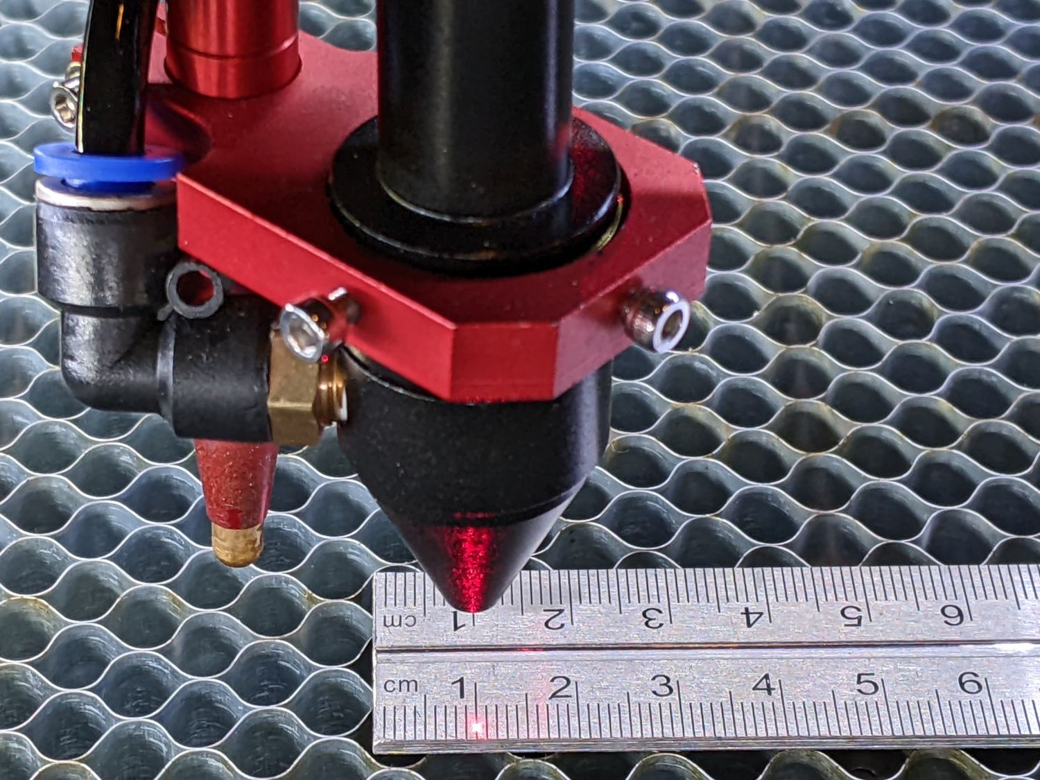
So I have a question regarding steps/unit and kerf offset.
Up until now I’ve not needed to be concerned about fitting items together and dealing with kerf offset.
So performing a couple of different types of kerf tests to determine what the value is, I’m getting stumped on what’s going on.
I did a 1" square with no offset as prescribed in the tests, but in the X I’m getting a measured average of 1.0004" and in the Y I’m getting 0.9965".
Since I’m so close in the X, it got me to thinking about the step/unit and how it plays out with the end results. From my perspective, if you dial in the step/unit to get it to cut exactly to that dimension, i.e., one inch, without accounting for kerf offset, then in reality the steps/unit could be off. Miniscule probably, but still off.
Now with my background in CNC machinery, where the bit size can be also be offset by half the diameter of the bit, it cuts exactly that from the drawn or coded line. The difference in determining steps/unit in that arena is that you don’t have an unknown nor does it matter to do the determination. What I’ve done in that setup is to simply set up 1-2-3 or 2-4-6 blocks, give the machine a distance to travel that matches one of those sides and check/verify the actual distance moved and recalculate the steps/unit accordingly. Easy peasy.
However, since I don’t know what the actual kerf offset is in the laser arena, it seems logical to me that this will be many trial and error permutations to get it right.
If I draw a line and tell LightBurn to move that distance from end to end, I’m guessing I could also set up the same blocks and measure off the side of the laser mount with a dial indicator as on the other CNC machine. Check and adjust, since I’m not attributing any laser offset, just purely movement.
Then I could do a cut and measure accordingly. Now comes the fun part, X & Y of the laser beam isn’t a perfect square AND LightBurn doesn’t allow for the different axes, only a one-size-fits-all kerf offset.
Have patience with me as I’m sort of OCD when it comes to stuff like this.
I do have a 24" dial caliper that I do measuring with so that’s not a problem to check the end result of “expected movement + kerf offset” to determine the actual offset. Seems that would be best to do on the longest line I can do with my laser bed setup.
- Stack all of my 1-2-3 and 2-4-6 blocks end for end
- Measure that amount
- Draw a matching line distance in LightBurn
- Have the Laser Mount move that amount via LightBurn
- Measure actual end result
- Set steps/unit as needed to get the movement as close as possible to the expected
- Do same for other axis
Then I think I could get a more realistic number for what the kerf offset equates to once I know for certain the head is moving accurately.
Am I way off in left field here? Is it really necessary to go to that much trouble? Sure I can play around with the kerf offset by trial and error but that won’t get me to an accurate part along with an accurate fit.

