I understand the concept with using a kerf (I think). After hours of cutting wood and acrylic I though I had a great fit. Lightburn test came out 0.10. I found my situation with acrylic to be 0.15 to 0.25 depending on how tight I wanted the fit. Printed 20 or so parts worked fine. Wet back to cut some more and that when the stuff hit the fan.
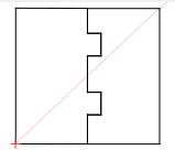
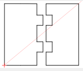
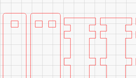
Using Acrylic and 0.15 which was a great result 2 days ago. First I printed out 1 set no kerf to make sure my design was ok and the result was as expected Far right.
Applied the above kerf on CO2 (blue) and could not believe the result.
Thx for the catch Mike. The way my eye/brain works (when it works) may have never noticed that. This file has always been in mm not sure how I changed it to inches. I was working on a file that needed inches earlier. I either saved and closed or finished then opened a new file and which closed the inch file and discarded - that was an easy file I didn’t need to keep.
I’m chasing my tail and evidently I have no idea what to do. I trying to use the kerf to get a snug fit. Hopefully both sides will be equal height.
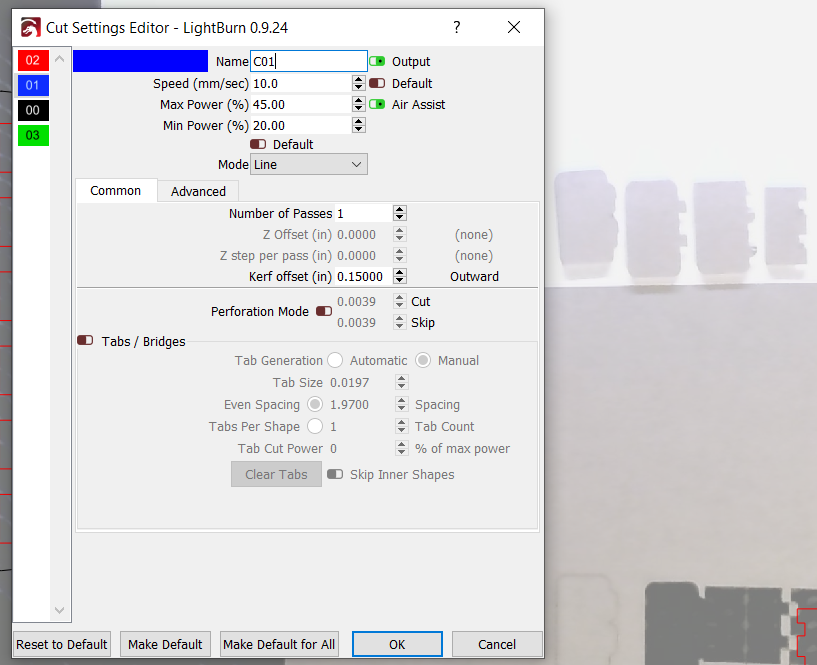
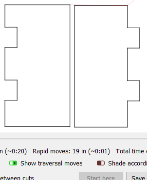
Preview Mode
I want a snug fit with these two pieces and they should be flush top and bottom.
Although now showing in the preview the tab layer is C00 - black which for now I am applying the kerf to. The grove piece is C01 - red. Staying in mm’s. (preview mode)
At one point in time about a week to 10 days ago I had the kerf snug to almost too hard to put together by hand. Now it appears that the kerf is not being applied to the cut. I double checked each kerf setting to make sure I am mm and the intended kerf is in the layer settings correctly.
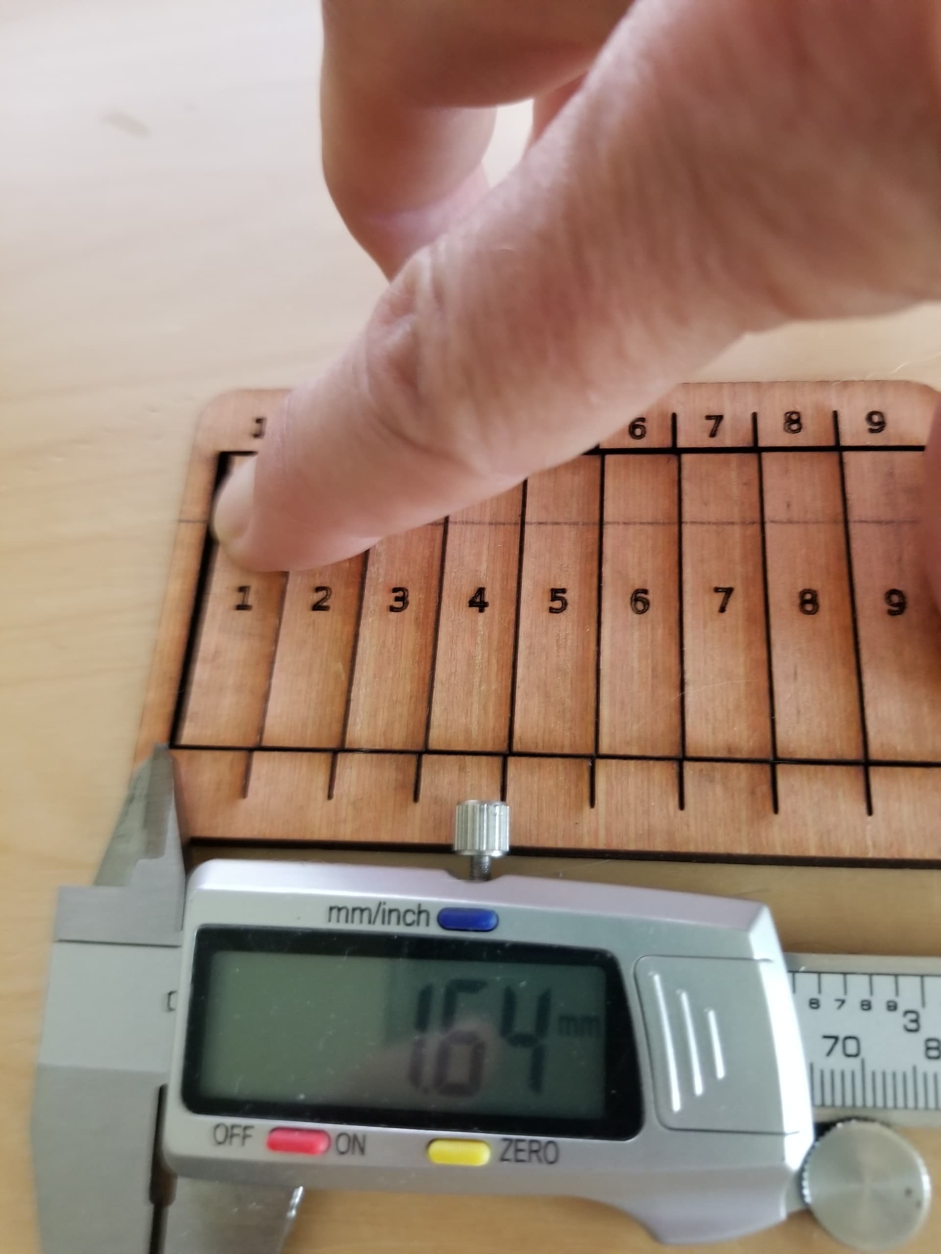
My LB kerf test cam out 0.10
I have put the tabs to include upper line and lower line in a 3 layer and applied the kerf to that layer only. Needless to say I am at a loss with getting this to work.
I need to use both on 3mm b. birch and acrylic. for now I am using acrylic. Micrometer at 2.93. The test was something here on the forum. I couldn’t readily find it. Nevertheless, on the 2.93mm acrylic I have set the kerf as far as 0.26 to -0.26. I and not getting a super lose or tight fit.
If you going to do that testing, then use the results. Might want to go over the Lightburn Documentation on how kerf works. Although it could be confusing to some. “Using outward kerf moves the laser beam outward, away from the shape, and using inward kerf moves it inward, into the shape.”
You may know this, but… If you cut a wooden stud to a certain length, you cut it so one side of the blade is on the outside of the cut line. This makes up for the kerf of the saw. If you cut centered on the ‘line’ you have lost 1/2 the kerf from the length of the stud. You are doing the same thing with this. I only mention this because you stated you tried the - and the +. If you understand kerf, you should be able to apply it properly.
In your situation, it’s a positive cut kerf. You want the ‘blade’ to cut the outer (+) edge of the material.
If you are building something that has a hole or something where another piece is mating like this coaster
It looks like an equipment pallet. All of the parts use a positive kerf, additionally the 'hole’s have a negative kerf. The blade is on the ‘inside’ of the cut hole.
Does that make sense? That’s how my pallet goes together
Don’t think I don’t understand you’re frustration, been there myself along with a boatload of others. You’ll get it.
Go to the numbers you came up with in your testing.
Are you applying kerf offset to only one of the 2 parts? Because that doesn’t work well at all. The part with offset applied will end up taller than the other and the tabs won’t fit quite correctly.
You want to apply 1/2 of the desired offset to BOTH pieces to get reliable results. If you’ve got a 0.008" kerf then you want offset to be 0.004" (outward) on each piece.
I didn’t think about applying to both sides. On the end cuts I just filled the difference on the smaller piece to make the top and bottom flush. I’ll work on that 50% when I get the further with this… more in the next reply.
Yeah, always do both pieces unless there’s some specific reason not to. It keeps the pieces in your example the same height and also if you have interlocking tabs that push together it keeps them the correct length. If you apply kerf to only one side then those tabs will be longer than the ones on the other piece and will leave little gaps at the end of the shorter ones.
Jack I really appreciate the extent you are going to. I am going to attempt to duplicate the example you showed. I did understand the wood/saw blade example and in the past woodworking life have often made allowance for kerf when cut several pieces in one piece of wood, thanks.
The numbers I stated was due to the fact I didn’t appear that I could “see” any difference in each cut, which there were about 12 cuts with different kerf in each cut. I couldn’t ‘see’ any difference in the gap. So I went to the extremes 0.26 and -0.26. It appeared there was no difference thus got me thinking the kerf wasn’t being applied…
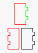
At first I was cutting both bottom figures applying the kerf to the black layer only. Last week This worked other than the height difference which I understood why. At that time I broke all lines apart changed layer color red with 3 sides (3 different lines).
I changed the tab side to green and began testing kerf on the green layer only - thinking I could trim off the excess on the green layer once I got the kerf set. Again there didn’t seem to be any difference in the ‘gaps’ of the tabs when I changed the kerf settings. I got to the point I would change the kerf, select OK then open and make the new kerf was set. I an going to LB and try and recreate the example
I didn’t even consider the length aspect. In this project that wasn’t all that critical, however, the height to being equal was and issue I needed to address. All progress stopped when the kerf settings worked a while ago and then the other day it appeared the kerf was not being applied to the cut. I am going to attempt to duplicate the kerf example shown above. Thank you. ( I know the thanks shouldn’t be put in - but it seems rude not the appreciate the help offered)
Kerf offset will not be applied to that green tabbed shape because it’s not a closed shape. Open shapes have no inside or outside to offset towards.
Only closed shapes will get offset.
ETA: If you are having trouble getting kerf offset to work, one of the first things is to verify that your shape is truly closed and not just a collection of lines that look like a continuous shape but aren’t really.
ETA ?. I duplicated the above with straight lines and it didn’t work. About to post there was a problem with LB or my laser. This is probably my problem. I’m going to do some more testing right now.
Once you’ve done your thing with the straight lines, select the shape and go to Edit > Auto-join Selected Shapes (Alt+J) and see if that closes it for you.
If do Edit > Select Open Shapes, it will show you which ones are open. If it ain’t closed, it ain’t gonna offset…
I don’t know if I was obscure in the photo of the kerf measurement. If you press them all together and measure the resultant gap. Don’t forget to divide by 10
I design it in a cad (freecad for me) and use parametric model parameters so I can change stuff around. I export it as a dxf file and load it into lightburn. I only use it for things that can get complicated in design, like finger boxes. I also like to be able to change a complex design by just changing one number, such as material thickness.
When I make my tabs and slots they are the literally the same size. Meaning if my kerf is correct the parts will be exactly like I specified. Since they are exactly the same in the dxf file, the will be exactly the same on the finished product. Having stated that, they won’t fit together since there is no clearance between the parts.
So, I did a little bit of lying, I do have a ‘clearance’ variable, usually 0.05 for plywood that is subtracted from certain parts for clearance of the joint.
Many of the ‘finger box joint’ programs that use kerf divide it by 2 and apply it to all the parts. Maybe because… keep in mind that, like the width of a saw is say, 2mm for simple math. So what’s the proper perfect kerf? If we cut down the center of the line we get 1mm taken off both sides of the cut. To get the proper offset we move the saw blade 1/2 it’s kerf. The same with a laser. I usually go to 1/2 if I have problems as an adjustment if the fit is too tight.
IMHO, the idea of a kerf cut is to get the exact size parts that are specified in the ‘engineering’ drawings. It’s not to adjust the cut, it’s to correct the mechanical for a proper cut.
This has been like practicing self dentistry - specifically a root canal.
OK where things stand right now. First off a huge thanks without the help I would have given up.
The problem is/was me. I didn’t realize I had to work with closed shapes, hence no adjustment with the many test cuts I made. 30 or 40 with small adjustments. The is a problem with my C01 layer - more in a moment on that. When I tried to duplicate the example above I used lines not noticing the pieces were rectangles, I am going to reconstruct that tomorrow, simply because I want to learn.
I mentioned above I had this working than I went in again and it didn’t work. That was because I changed the closed shapes which opened the shapes. I continued to use the open shapes with a huge amount of testing resulting in a total waste of time/material.
The acrylic I am using is 2.97mm, the kerf being 0.22 and the setting for each piece is 0.11 resulting in a very tight fit.
Some questions:
… If I combined both images on on 1 layer and set the kerf to 0.11 (1/2 of Kerf) would the result be the same as cutting on 2 separate layers with the setting at 0.11?
… Would the kerf work if I joined the two pieces as a single image with separation line/cut ending up with 2 pieces. The kerf setting would be set to 1/2 (0.11).
Lastly.
Problem with layer CO1. The odd shapes I showed above, rounded corners and tabs was caused by some setting(s) in my C01. Every rectangle I create has rounded corners when I preview the image.
Is there a way to reset a layer to LB original settings? It would appear I have set the current (wrong) settings to be default.
Again thanks.