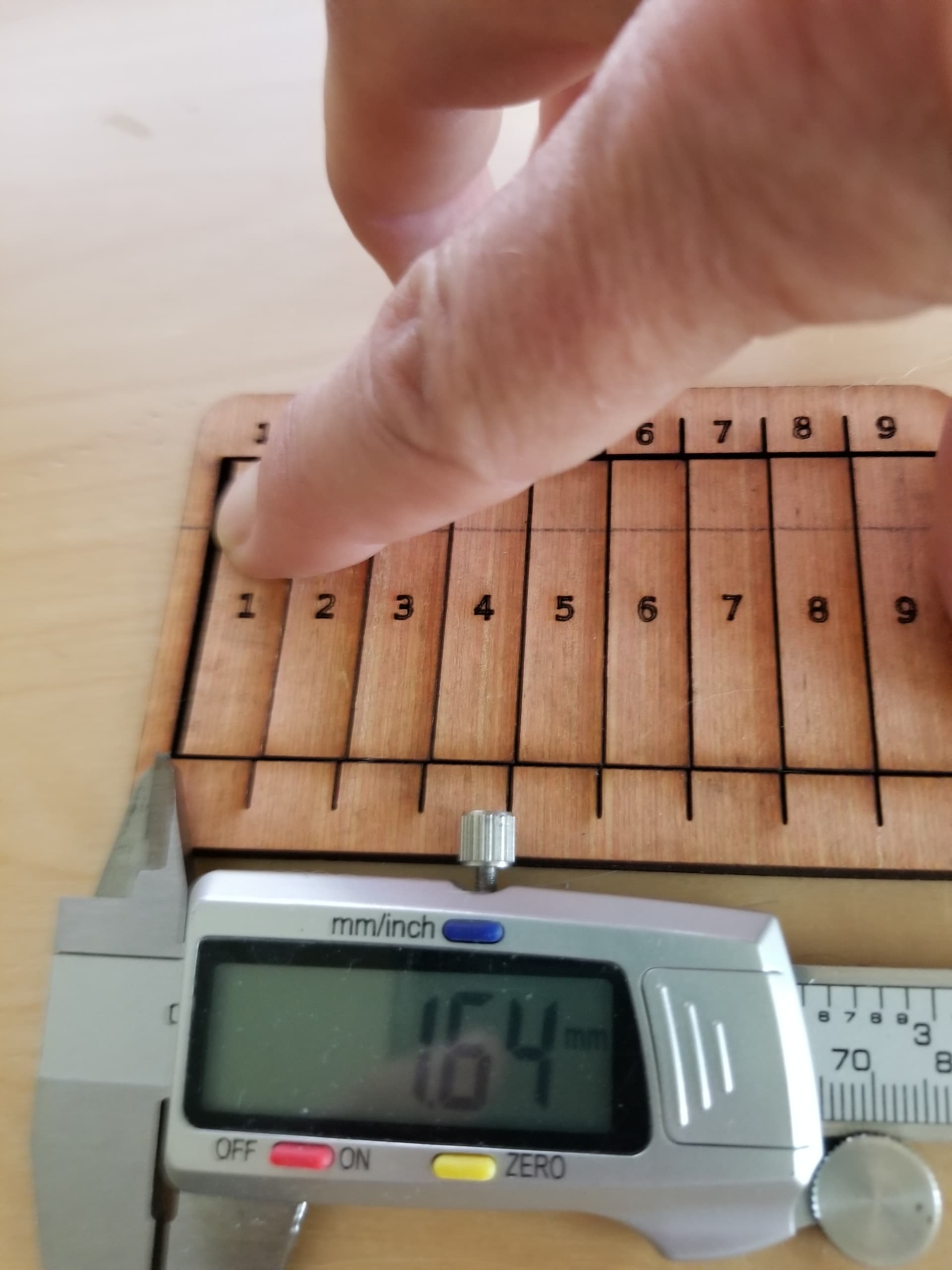
I don’t know if I was obscure in the photo of the kerf measurement. If you press them all together and measure the resultant gap. Don’t forget to divide by 10 
I design it in a cad (freecad for me) and use parametric model parameters so I can change stuff around. I export it as a dxf file and load it into lightburn. I only use it for things that can get complicated in design, like finger boxes. I also like to be able to change a complex design by just changing one number, such as material thickness.
When I make my tabs and slots they are the literally the same size. Meaning if my kerf is correct the parts will be exactly like I specified. Since they are exactly the same in the dxf file, the will be exactly the same on the finished product. Having stated that, they won’t fit together since there is no clearance between the parts.
So, I did a little bit of lying, I do have a ‘clearance’ variable, usually 0.05 for plywood that is subtracted from certain parts for clearance of the joint.
Many of the ‘finger box joint’ programs that use kerf divide it by 2 and apply it to all the parts. Maybe because… keep in mind that, like the width of a saw is say, 2mm for simple math. So what’s the proper perfect kerf? If we cut down the center of the line we get 1mm taken off both sides of the cut. To get the proper offset we move the saw blade 1/2 it’s kerf. The same with a laser. I usually go to 1/2 if I have problems as an adjustment if the fit is too tight.
IMHO, the idea of a kerf cut is to get the exact size parts that are specified in the ‘engineering’ drawings. It’s not to adjust the cut, it’s to correct the mechanical for a proper cut.