Bob - Hank is right, and there’s no reason you should have to put your cuts on different layers with only part of them having the kerf offset. Can you post the file you’re trying to use?
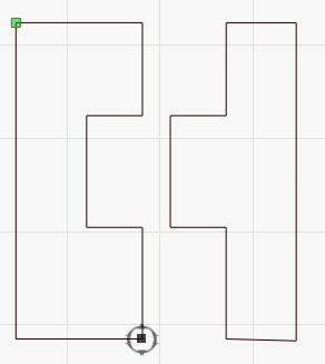
The file you emailed has a weird extra line in it, which could conceivably cause an issue:
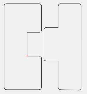
Having said that, I applied a 1mm kerf, just to exaggerate it, and this is my preview:
Both parts are very clearly offsetting properly, so I’m not sure what’s happening.
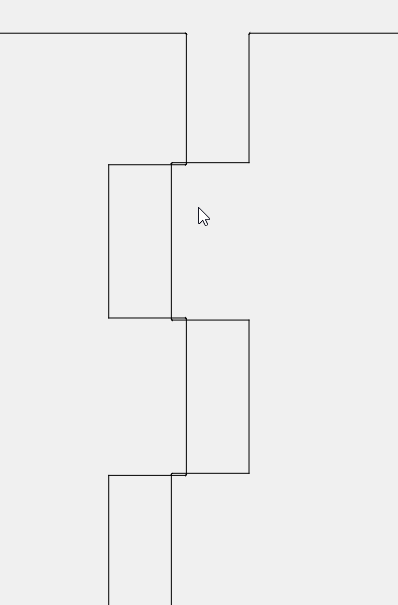
Even with 0.01" (in inch mode) I see definite offsetting: (you can see the rounded corners)
Are your kerf amounts correct? This file has the kerf set to 0.00071 in, which is about 0.018mm. A typical beam width is 0.1mm, so it feels like you’re off by a factor of 5 to 10.
All is well…I hadn’t taken it back up to a larger offset since I started to auto join. One question should each of these parts be auto joined separately or doesn’t it make a difference?
That shouldn’t make a difference unless there are spots where it’s ambiguous as to what should get connected - like if a bunch of lines met at a cross-intersection and shared a point, then you’d likely need to guide it. Usually it just works.
DXF files often need to be joined - plenty of software that exports them just does a bad job of it, at least partly because AutoDesk is tight-lipped about how to export them correctly. Oh - and you’re welcome.
If you’re already in Fusion 360, use the CAM view, define a tool with a diameter that matches the kerf width, use the Universal Laser post processor to export a DXF, and you’ll get perfectly fitting parts.