Ran the test and measured the squares.
Did the calculation and added the number to LB.
Did a new test and noticed that it fitted nice on one side, but was not able to fit on the other side.
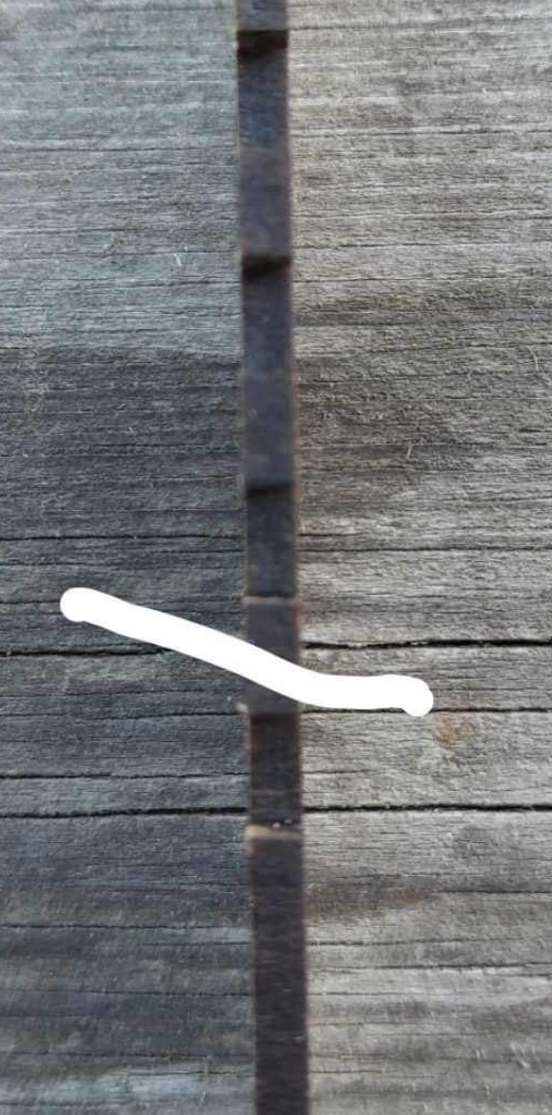
Had a look at the cutting around the square and noticed that the cutting was a bit tilted. (If this is the right word to use) See picture.
It’s not on all sides.
It’s not much, but enough to mess up a little bit.
And that’s why it does not fit on one side.
I know the beam isn’t round or square since this is a diode. On their web page the spot Size is: 0.08mm*0.06mm
Its a Ikier 24w I’m using.
Will it help to adjust the focal point?
I have used the autofocus and it cuts really nice.
Or shall I run a new test and measure the widest part of the square?
Basically all the Chinese diode manufacturers either flat out lie about their spot dimensions or they have an unrealistic measuring protocol.
My Ikier 24W is closer to .15 x .25, although I have suspicions mine is a particularly bad example. If I thought I had a chance of approval, I’d request a replacement. Other than a marginal beam, it runs good, so I leave well enough alone.
I have run DOZENS of tests to dial in ideal focus and kerf on multiple materials. I evaluate using a good crack ruler and a microscope, good calipers, feeler gauges, and/or actual test fitting.
Wait til you start noticing the Z taper…
Best advice I can provide is to test, test, and test again. Then, orient your critical-fit cuts at approx 45 degrees to the X/Y machine axes to minimize the difference from x to y…and test some more… It will enlarge the kerf, but piece-to-piece fit will be more consistent once the offset is dialed in.
I’m not sure I understand what you mean by this. What the picture is showing is not obvious to me.
An asymmetric focus dot won’t tilt anything so not following the relationship. It will make the kerf in one dimension different than in the other.
Are you referring to the angle of the cut due to a wider kerf at the top of the burn relative to the bottom? If so, this will be virtually impossible to eliminate as it’s inherent to how certain materials burn with diode lasers. You can experiment with different focus heights to see if you can reduce this effect. Various levels of air assist may also make a difference.