Hello! First post here, so not sure if this is the right category. Looking for help as well as showing off what we believe is the first high power metal cutting fiber laser powered by LightBurn.
Our company built a Carbide3D-based 1KW fiber laser that is controlled with LightBurn and uses a TF-6225 controller. We finished the build yesterday and are now trying to get it tuned.
We are really struggling to figure out a good starting recipe. It doesn’t help that the Trocen manual is pretty horrid, but I digress.
Love the LightBurn software since it can connect to the controller via USB as well as ethernet. Without LightBurn this thing would be pretty useless.
Right now we’re finding it hard to get perfect circle shapes in addition to the Z axis ‘jittering’ for the plate height tracking feature. Playing with the accel and jerk settings doesn’t seem to be helping at all.
I realize this may be the only machine of its type on this forum compared to normal Co2 lasers, but help is appreciated! Thank you!
Some machine specs:
48V at 1.7 amps to all steppers (Nema 23)
15mm wide belts on X and Y axes.
Leadscrew on Z axis.
RF height sense amplifier for plate tracking in real-time.
Calculated distance per pulse for each axis:
12.5 µM for X and Y axes (3200 pulses per rev @ 1/16th microstepping)
5 µM for Z axis. (1600 pulses per rev @ 1/8th microstepping)
Here are some pics taken of the current settings on the controller. This is essentially all of the options on the machine. There is no pic of the Y axis parameters, as they are the same as the X axis pic below.
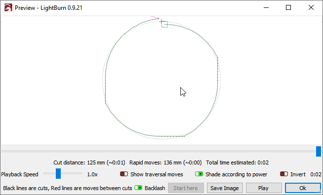
After some more experimenting, here is a pic showing how the circle shapes are turning out regardless of the diameter of the circle and regardless of the setting we put in for Curve Tolerance in LightBurn settings:
For some reason, it’s as if the Y axis continues in a straight line for no reason and it does it 180º apart.
Could it be that 12.5 µM per pulse distance is too high causing this issue? @LightBurn We’ve confirmed the pulleys are tight and Loctited in addition to having the belts tight. We’ve played with the curve tolerance setting and it doesn’t change the outcome. The circle was drawn in Lightburn and not imported as a DXF.
We have not found backlash in the system either.
If you need us to try using LaserCAD to test, we can do that too I think by setting up a virtual machine.
On another note, is it possible that having the pulse distance incorrect in even a slight amount would cause this?
The straight lines are caused by backlash on the X axis - likely incorrect belt tension, but could also be the stepper driving the X axis belt has a loose pinion or the set screw holding it in place is loose. If I simulate backlash, you can see exactly the same effect:
Yes, I mentioned that we’ve already confirmed it’s not backlash and that everything, including grub screws are tight. We spent a whole day just going over the belt system.
I know you said it, but I also know what I see, so I would double check. If you have an oscilloscope, you could put one on the X axis step signal and verify that steps are being sent while the axis is not moving, which would prove that it’s mechanical. Or, if there were no steps being sent, that would prove that it was something in the file or electronics.
I assume the circle on the preview, and on the controller display looks like a circle?
Great minds think alike. I was wondering if we could rig up a pulse counter and hook it up to the X and Y drivers and see if the pulses match up. Because, for a 360º shape, there should be an equal amount of pulses sent to the motors provided that lead-in is turned off?
@LightBurn I’m attaching a UD5 file created in Lasercad and one UD5 file created in Lightburn to see if you find anything that sticks out that would cause this.
Both files are of a 50mm circle with 0.010 curve tolerance, 50mm/s speed, 100% max power, and 11% min power.
There are a few small differences in the file in the setup, but the actual cutting commands are quite similar. Nothing in either file shows anywhere that should be flat on the sides. When you run a circle in LaserCAD, are you also getting the flat sides, or no?
And yes, for a circle, I’d expect the pulse counts to be damn close for X & Y. There could be a tiny amount of difference, but basically a rounding error.
Probably not - The minimum signal width for the controller is going to be more like one to two microseconds. The 0.5ms shown is 500 microseconds. You’ll need something quite a bit faster.
Daaamn - that’s pricey. An Arduino could likely do this - you don’t need GHz precision, just 100 KHz or so, possibly as high as 1 MHz, but that’s unlikley.
An arduino or Pi sounds good too! Not sure where to start though.
I was wanting to find out what kind of chipset these Chinese controllers use to figure out the maximum amount of pulses they can generate in their stepper ISR, so I would know theoretical max speeds without stuttering. I can’t risk tearing it apart though to find the chip.

 Thank you!