Hello, I have a DIY XYZ table connected to a Arduino Uno and a E80 NEJA laser. I am trying to burn an image of an elk drawing that is in black-and-white at 3000 mm/min at 20% power. My Arduino setting for X & Y max speed is 3800 mm/ min. WHY does the X axis speed keep changing during burning of the darker areas?? I would think that the X axis would stay at the same speed back and forth and the laser would just change its output power.
You have Fast Whitespace Scan turned on?
Hello Mike, I’ll have to check out fast whitespace. I’m not sure what it is but I’ll check it out. Thanks for your reply.
Carl
Hi Mike, I checked and I do have whitespace turned on. I can see how the laser speeds up between the white spaces, but it still seems to slow down very much during the part of the image that have to be burned. When I jog the X axis at 3000 mm/min I can hear the tone of my X axis stepper motor. During the image burning, it seems to slow down slower than the tone I hear when I’m jogging it. Thanks again for your help.
Carl
You don’t hear that tone immediately, right? It builds up as the head moves? Are you accounting for acceleration & deceleration? Except foe Galvo, I know of no machine that can reach full advertised speed in an inch. At least none we cah afford.
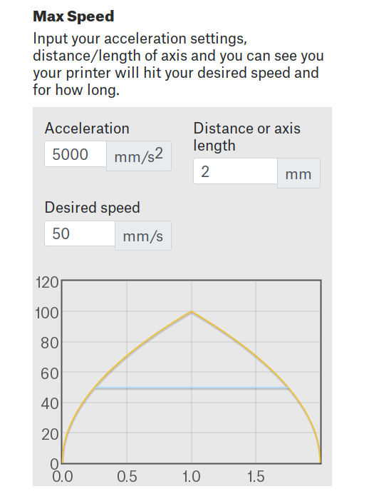
Use the RepRap Acceleration Calculator to discover how much distance the axis requires to reach the commanded speed at a give acceleration:
Get the X axis acceleration from GRBL’s $120 parameter.
For example, my CO₂ laser has an X axis acceleration of 5000 mm/s². It can hit 3000 mm/min = 50 mm/s in about a quarter of a millimeter:
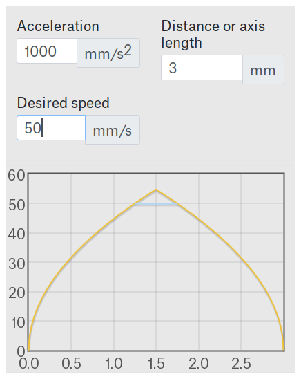
Limiting the acceleration to 1000 mm/s² increases the distance to 1.25 mm:
Feed in the acceleration for your machine and you’ll discover where those tones come from. The machine must accelerate after dark-to-light edges and decelerate before light-to-dark edges, which is why Fast Whitespace Scan may not actually speed things up for complex images with very short distances between the edges.
Hello Esnisley,
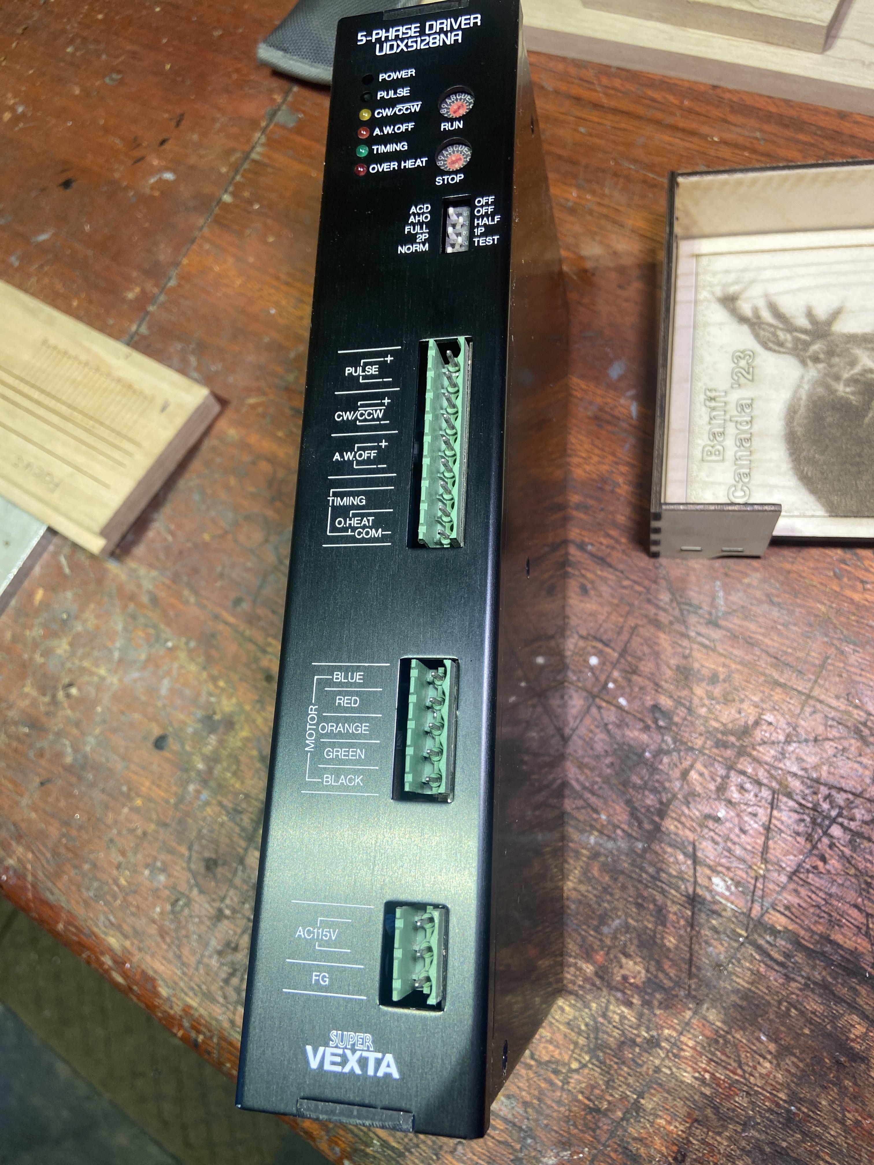
Thanks for the info, just so you know I have a 5 phase stepper motor on my X axis which is 0.72 deg per step driving a 5:1 planetary reduction. Maybe that is why I’m hearing different tones between the whites and darkness. I’ll do more testing and research.
Carl
Mine will reach 1500mm/s in about an inch…
@Cjsolar - what kind of steppers do you have that are 5 phase?
![]()
Should have said “none I can afford”. ![]()
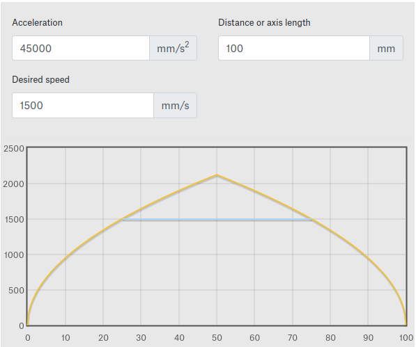
@jkwilborn I stand corrected, I was reading the graph wrong. Mine should reach top rated speed in about 5mm. A=1000, D=25, S=100, all mm/s values.
On the NEJE in your profile? That seems … exotic. What other changes have you made that we don’t expect?
In any event, the type of motor is largely irrelevant, as the controller knows only the acceleration and speeds settings, with the results shown by the RepRap calculator. If the acceleration settings are too low, you’ll hear the speed ramp up and down.
Given the high stepdown ratio, the usual diode-laser acceleration settings are likely very low. However, because stepper motor torque varies inversely with speed, the motor can’t accelerate / decelerate as much as you may need while running at the high motor speeds required to reach typical laser motion speeds.
The Arduino Uno has an 8 bit microcontrollers that’s limited to producing stepper pulses up to about 40 kHz, which puts an upper limit on the motor speed. Divide 40×10³ step/s by the GRBL $100 X axis step/mm value to find the maximum speed in mm/s, multiply that by 60, and it should be lower than the GRBL $110 value. The machine’s mechanics will probably set a lower limit for $110.
You must determine the speed and acceleration values by experiment, which always involves motor stalling and various weird noises. No harm comes of that, but your cats & dogs may have a bad time. ![]()
Mine is a China Blue 50W, so it’s a normal co2… A bit of tweaking to get there, but relatively low cost.
![]()
Hello everybody, first I’d like to thank everyone for their support. I was able to get the five phase stepper motor from work from some decommissioned equipment. I wasn’t sure if being a five phase stepper would make any differences. I’ll go through and look at some of my GRBL settings to see where I’m at.
Carl
Two differences, smoother stepping and higher torque.
Smoother stepping probably no difference, unless your dot size is in the micron range (less vibration).
More torque means higher acceleration rates, reducing burn time and requiring less overshoot amount. Downside is that the power supply has to have the reserve capacity for the current surges.
Stepper motors are constant-power devices that don’t behave like DC motors. The stepper driver controls the motor winding current to precisely position the rotor for each (micro)step, so the only difference between “noodling along” and “accelerating like crazy” is the step pulse timing.
With that in mind, however, everybody assumes the stepper driver’s “peak current” setting means that’s the maximum current it will draw. Which is true for a single winding, except that there are two (or five) windings and each winding can draw that peak current.
For ordinary two-phase steppers, the maximum total current for both windings can be √2 higher than the “peak” current and, because the motor can be stopped at that point in its rotation, the power supply must be capable of delivering 40% more current than everybody expects to each stepper driver.
So, yeah, overspecifying the power supply is a good idea. ![]()
Hello, thanks for the info. I was checking my settings in GRBL and the $120 = 160, X acceleration mm/sec^2. I was thinking, and I’m going to do another test with some white and black stripes an inch wide to see if the speed changes much during the totally black stripes in Lightburn.
Thanks, Carl