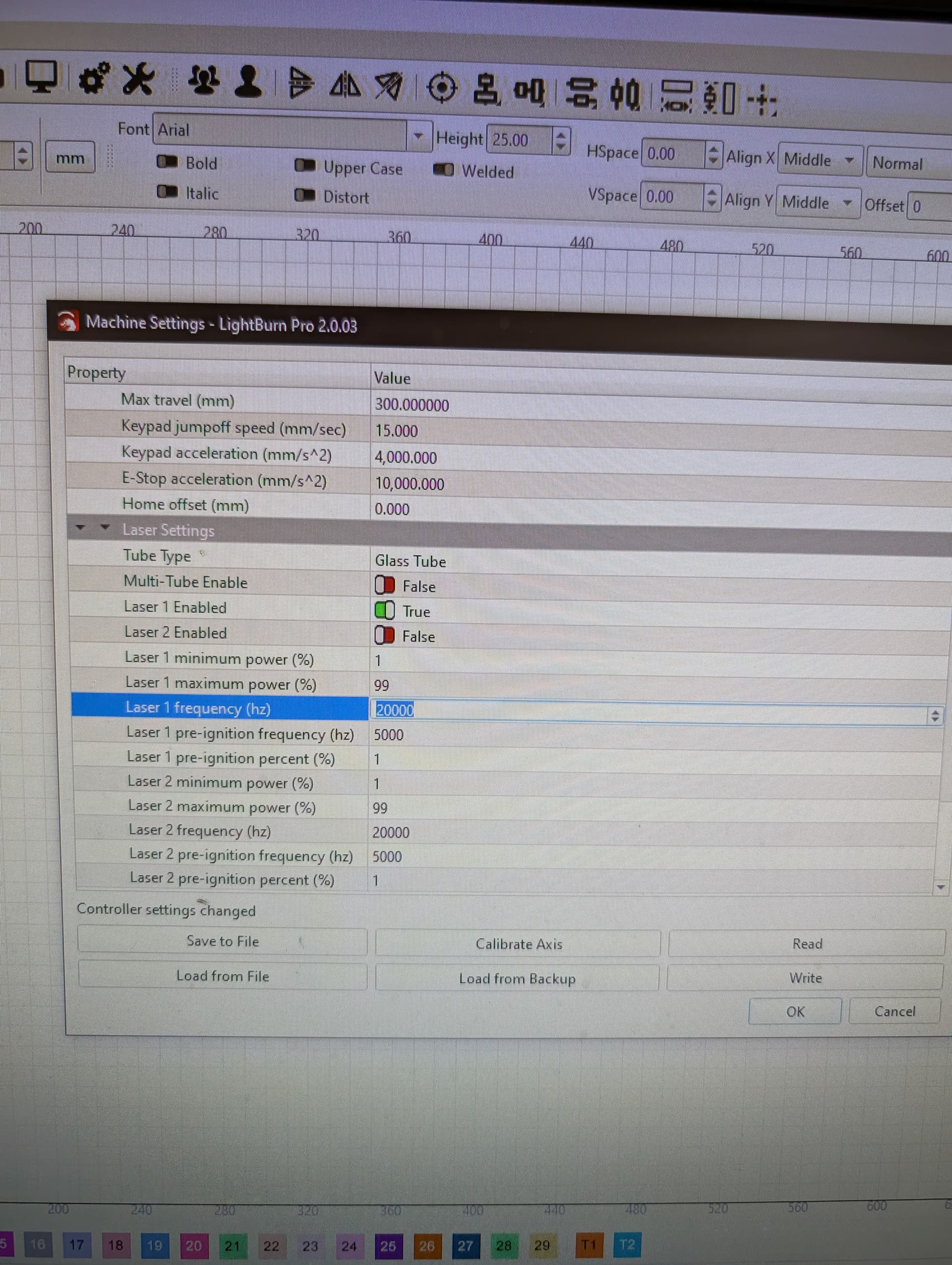
If we have a glass tube laser, do any of the settings in this page have an effect?PXL_20250930_105703153|376x500
If that is what is showing in your Lightburn, I would say all of them do. That is why they are there.
Those are set and forget settings. If you are thinking of changing them, DON’T! Not until you know what they are for and what will happen if you change them. And make a backup no matter what you do.
The Laser x frequency values control the corresponding carrier frequency for the LPWMx outputs to the high-voltage laser power supply IN terminal. The power supply isn’t too fussy about the PWM frequency, but the default works fine and there’s no reason to change it.
The pre-ignition entries apply to RF tubes and probably don’t affect the glass-tube output, but ya never know.
The Laser x min power and Laser x max power limit the power settings in the LightBurn layers. It is unclear whether the controller clamps the layer power or interpolates the entire layer range to fit, but there seems no good reason to change them.
The Ruida manual for your controller may include more verbiage about some settings:
Pre-generation pulse scale: When the laser is RF-laser and it’s need to pre-generate PWM, then set the Pre-generation Frequency and the Pre-generation pulse scale.
As @MikeyH says, DON’T. ![]()
2 Likes
“As @MikeyH says, DON’T. ![]() ”
”
Awe, you guys are no fun…!
Well, we did change the frequency setting; we read somewhere that 20KHz was fine for acrylic, but that 5kHz or even 1kHz might be better for MDF.
So we tried it…![]() …and it is! The cut edge seems far sharper and smoother. We cut hardly any Acrylic by comparison, so we’re sticking with it…just remind me in 12 months when I come back to say " acrylic is not cutting properly" that we need to changed it BACK to 2okHz!
…and it is! The cut edge seems far sharper and smoother. We cut hardly any Acrylic by comparison, so we’re sticking with it…just remind me in 12 months when I come back to say " acrylic is not cutting properly" that we need to changed it BACK to 2okHz!
2 Likes
Put it on a Post-It note and stick it tomyour keyboard. ![]()
I dug into the effect of PWM carrier frequency on tube current a while ago. It may be more than you really want to know:
Changing the PWM frequency probably doesn’t do what you think it does, but as long as it gives you the result you want, go for it.
Ah, but our laser isn’t like other boys…the control signal doesn’t go via PWM…we are on an Analog signal.
Still haven’t managed to figure out why. I’ll go read the article now…
Edit: I’m reading the article now. It may as well be in Mandarin. I’d say “We really must get an oscilloscope”…but then I’d just be staring at a round screen and not understanding it, instead of a rectangular one.
Short version - any chance of an idiot’s guide?
1 Like
The PWM carrier frequency has no effect on the output from the analog (L-AN) terminal: perhaps you’re seeing what you want to see.
Been there, done that! ![]()
Not “idiot”, just a bunch of stuff you’ve never considered before and the vocabulary is unfamiliar.
A quick intro …
The high voltage power supply adjusts the tube current according to a signal from the controller. That signal can be either:
- An analog voltage between 0 V and 5 V
- Digital pulses at 0 V or 5 V, not between
For the analog signal, 0 V = no current = 0% and 5 V = maximum current = 100%. The voltages are approximate, but that’s the general idea.
The digital signal is a repeating pulse at a fixed frequency (“carrier frequency”) with its duty cycle setting the tube current, which is called pulse width modulation = PWM. The duty cycle is the ratio of the time at 5 V to the total cycle time = 1/frequency. A duty cycle of 0 (always low) = 0% and a duty cycle of 1 (always high) = 100%. Again, those are approximate.
The power supply can accept either of those signals on the same terminal because it has filter converting the PWM signal to the equivalent analog signal; an analog input signal passes through the filter unchanged.
The filter has a cutoff frequency around 200 Hz, with signal frequencies far below that defined as “analog” and signals far above it as “digital”. The default Ruida carrier frequency is 20 kHz = far above 200 Hz, so the filter output is a smooth, clean analog signal. That’s the straight green line along the bottom of this scope shot:

You can set the PWM carrier close to the cutoff frequency, but the filter will not produce a smooth analog voltage.
The green wave shows the result of a 5 kHz carrier:

This is a 1 kHz carrier:

Whether those irregular currents produce usable results depends on what you consider usable.
To further muddy the waters, it seems my KT332N controller has an internal PWM demodulating filter converting the digital signal on its PWM terminal to the corresponding analog signal on its L-AN terminal. Other controllers have hardware DACs producing a better-quality signal.
Make any more sense?
![]() slight_smile: Make any more sense?"
slight_smile: Make any more sense?"
Not right now if I’m honest, but then it’s 8am, I’ve just woken up and I can barely move for the Parkinson’s. snip
There was more detail than I should have shared here. You don’t need to know.
I think I get analog, that is the simple one…voltage applied between 0 and 5 equates to current delivered of 0 to 100%, so in my layman’s world, 1v = 20% strength, 2v = 40% strength, etc…
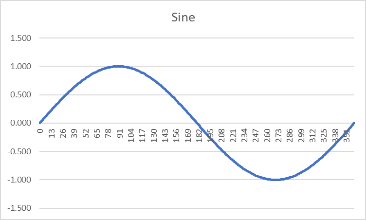
So, switching to digital, imagining a sine wave (I know, the two ideas are incompatible, but bear with me for now). Cycle through 360° and the value of sine moves from 0, through 1, down to -1 and back to 0. If it does that once per second, that’s 1Hz, correct?
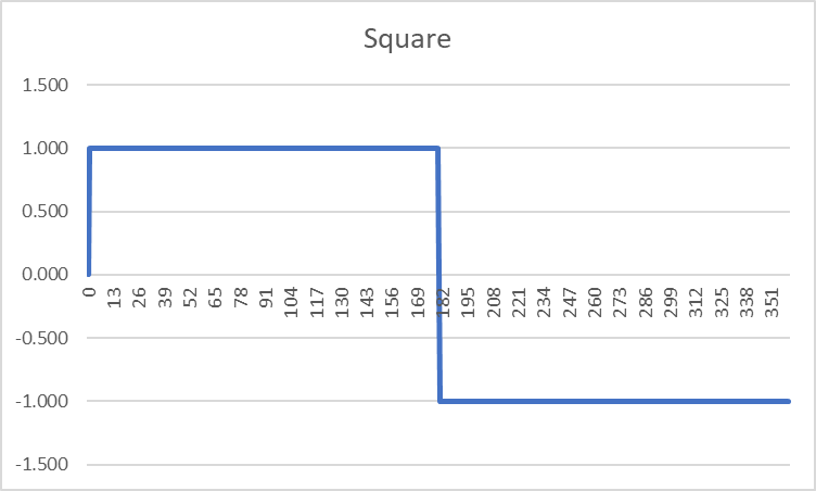
So replace the sine wave with a square waveform (so now we CAN do digital)…the first half of the cycle is “on” and the second half “off” (but the second half of the cycle is negative…I assume this is filtered so that it’s effectively zero?)
Question; are the pulse duration and the “off” duration always equal? I’m just wondering about your “Duty cycle = 1/frequency”…with the square wave is there a possibility of an “uneven” pulse, so that it was on for 75% of the time and off for 25%…which to my mind would mean the duty cycle was 75 %, even though the frequency hadn’t changed…
Second question; If I stick a multimeter across the PWM output, the max reading when the laser is set to 100% power is just shy of the 5v (about 95%) is this some effect of the duty cycle?
Hang on…I just realised the difference between pulse and beam lasers in Elite…this conversation just got cooler/nerdier depending on your point of view…![]()
I suppose the only really important questions are these; what do these fluctuations in current mean for:
the laser, in terms of performance, durability (and safety)
the actual cut/etch of the material?
Exactly!
The trick is to shift the sine wave up so the lower limit is 0.0 and rescale it so the upper limit is 5.0, whereupon the amplitude is the voltage at the (analog) L-AN terminal. The amplitude at what were the zero crossings is now at 2.5 V.
Which will look something like the cyan trace at 2 V/div:

The tube current is the green trace and the gnarly behavior as the tube fires came as something of a surprise.
The L-AN output produces an analog voltage corresponding to the layer power percentage, which will be constant across an entire engraving scan line.
Conversely, the sine wave in that scope shot came from a grayscale image test target with (wait for it) a sine-wave gray pattern scanned at 100 mm/s:

Scanning (“engraving”) that target at different speeds produces sine waves at different frequencies, which is how I figured out the power supply filter’s behavior.
Almost exactly! ![]()
Again, shift the square wave up so the baseline is at 0.0 and rescale it to put the top at 5.0. Now the square wave has an average value of 2.5, because it has a 50% duty cycle: half of one complete cycle is high and the other half is low.
The controller emits the square wave on the (digital) PWM terminal. The filter in the power supply does the averaging to recover the 2.5 V, which sets the desired 50% of maximum tube current.
If the waveform was high for only a quarter of the cycle (so it’s no longer a “square wave”), the average value would be 1.25 V and the tube current would be 25% of maximum.
If it was high for 3/4 of the cycle, the average value would be 3.75 V and the tube current would be 75% of maximum.
In all those cases, the cycle’s frequency remains constant and the pulse width determines the duty cycle. The (constant) frequency is the “carrier” and the (variable) pulse width is the “information”, which is where the name “pulse width modulation” = PWM comes from.
Now, make the PWM carrier frequency much much much higher than the engraving speed, say 20 kHz. Engraving at 50 mm/s makes each millimeter 20 ms “wide”, the PWM signal will have 400 cycles across each millimeter, and the PWM output will change 400 times during each bar.
The controller can change the duty cycle = power output for each cycle, varying the laser tube current to produce a grayscale image. Scanning the same target with the power supply connected to the (digital) PWM terminal as above produces (pretty much) the same result as when it’s connected to the (analog) L-AN terminal.
The cyan trace is now the (digital) PWM output:

You can’t see the individual cycles, but when the blur get increasingly solid around 5 V, that’s when the tube current (green) approaches its maximum value.
The scope shot up there shows “ordinary” = non-image engraving with constant power. The PWM duty cycle remains constant across the entire bar.
There are some nuances, but that’s probably enough for now … ![]()
1 Like
Love the writeup. Being an electronics guy, I read it with a critical eye. ![]() I found nothing to debate in there, good job!
I found nothing to debate in there, good job!
Shoving the AC up +2.5v is called adding a DC offset.
Hope you do not mind my summary:
Digital (PWM): Fixed frequency and the on/off time is varied (amplitude is fixed).
Analog: Fixed amplitude and the frequency is varied. As the frequency increases, the on time (per second) increases. For those that want to challenge this, remember capacitor reactance goes down, increasing the current flow, which increases the voltage across the load.
Forgot to account for switching a bunch of wiring and a capacitor (tube) before the tube fired, did we? I would too. I bought a 200MHz Rigol unit not remembering that it would show EVERYTHING in the waveform. Then I bought a DSO150 to reduce information overload. ![]()
Did you also notice the ringing when it shuts off?
“Now the square wave has an average value of 2.5, because it has a 50% duty cycle: half of one complete cycle is high and the other half is low.”
Only bit that foxed me. So the duty cycle isn’t equal to 1/frequency any more? Or did the frequency change from 1Hz to 2Hz?
As a company, we do more cutting than engraving. The boss read somewhere that the lower 1kHz frequency was lower heat, and thus gave better results in MDF, but the higher 20kHz frequency was better for Acrylic, where the heat melts rather than burns.
This was borne out by our tests, even a blind test where one of us cut pieces and had the other choose which was “best”.
Is this likely? Possible? Or are we fooling ourselves?
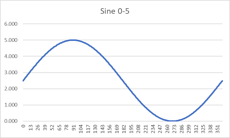
I was trying to make the adjustments to my Excel-generated graphs to give the correct 0-5 volt values. I understand maths more than electronics, so this helps me visualise what Ed and Mike have been kindly trying to teach me…
The sine wave was easy*; the excel formula is;
=(SIN(RADIANS(A2))+1)/2*5
All you need is to put the values 1-360 in column A starting at row 2 and the above one cell to the right in column B. and you get;
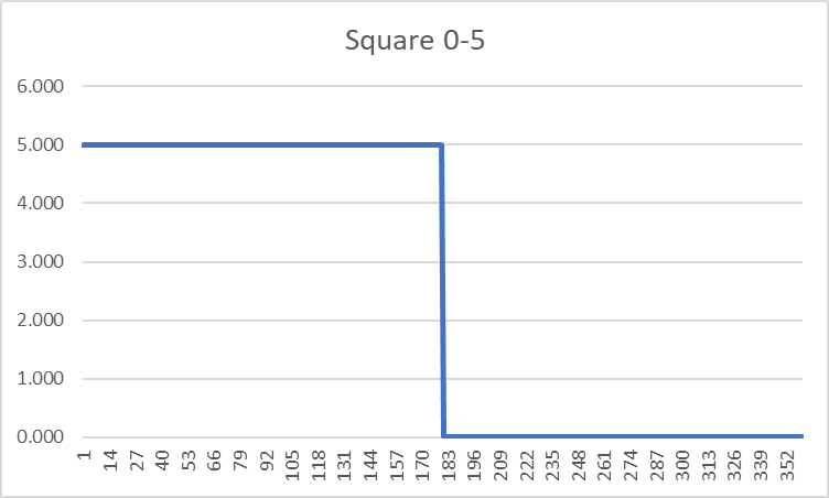
I’m struggling a bit more with the square wave…this formula;
=((ROUNDUP(SIN(RADIANS(A2)),0)+1)/2)*5
produces this graph
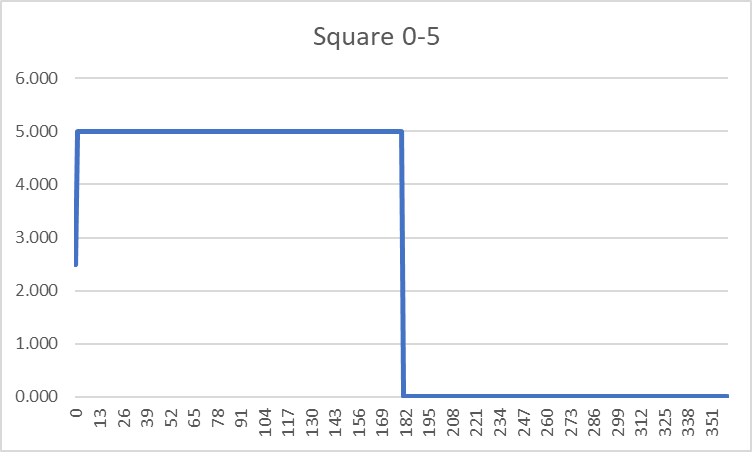
Which at first LOOKS right, but the values where sin() = 0 give a result of 2.5.
Now I THINK this may be closer to a “real life” interpretation of a square pulse wave rather than a precise mathematical one; in maths, the values should be 0 or 5…but in reality, there is no such thing as an “instant switch” from 0-5…it takes a non-zero amount of time, (even if it is measured milliseconds). Which gives rise to the other property we often see in Lightburn - “PWM Rising Edge Valid”.
Am I right?
*easy - for me. I’ll admit the need to convert to radians is a pain…I understand why Excel uses it, and it has it’s place…but it also adds a barrier to those with high school education who pretty much were taught exclusively in degrees.
If you were to write the formula in your maths text book it would be;
y=(sin(x)+1)/2*5
You can simplfy it further to
y=(sin(x)+1)*2.5
but I find leaving it as the original explains more what the maths is doing which is;
Sine values run from -1 to 1. We want a voltage output range of 0-5v. The easiest way to do that is to first get a range of 0-1, and then multiply by 5. (so now we know our last operator will be *5).
And to convert a range of -1 to 1 to a range of 0-1? Well first, we bump it up the axes by 1, so the range is 0-2…and then simply divide by two to get our 0-1 (which we can then multiply by 5)
Ha! “Pride cometh before a fall” says the Bible. The error was all mine…I’d put the values 0-360 in column A…but of course as far as the sine function is concerned, that’s a step too far since 0 and 360 are the same “point”.
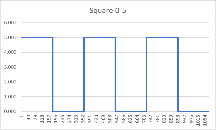
1-360 and it works perfectly!
Looks kinda wrong though…your brain wants to “fill in” the missing rise or fall…but if you extend the graph to three cycles (1-1080) it looks like the pulse wave you’d expect…
Hauling this thread back to the topic (and accepting that the deviation was 1. my fault and 2. very interesting)…this pre-ignition parameter…if you remember many moons back (hellfire I just looked and it’s almost a year!) the issue we were having is we had been using our laser at 6% quite happily…and then suddenly we weren’t marking the work at that strength. The speed hadn’t changed so we assumed the laser was showing it’s age and bought a new one - only to find that it wouldn’t fire below 11% either. At the time you (I think it was you @ednisley?) said we might have just been lucky (unlucky?) and that our original was an “enthusiastic” laser.
I accept we have a glass tube not an RF laser…but is it beyond the realms of possibility that this “Pre-ignition” value is some sort of “warmup” value that might allow firing at lower power settings?
IMO, no.
The KT332N in my machine has three choices of Tube type:
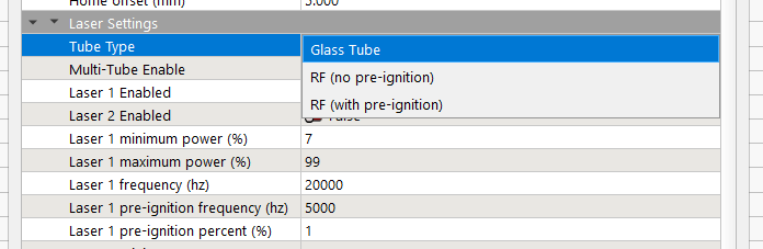
Evidently you (well, I) must select RF (with pre-ignition) in order for those values to take effect, which suggests the controller does not apply them for the other two choices.
Given that the machine has a glass tube and I’ve never changed those values, if they are doing anything, then they should have been doing it all along.
However, none of the myriad scope shots I’ve taken show anything other than the ordinary 20 kHz PWM carrier. Nothing else appears at any point in a scan line.
The power supply doesn’t know anything other than what arrives on its enable (H or L) and IN inputs. The controller disables the power supply when it’s not supposed to be firing and that works exactly as you’d expect: an active PWM signal does not cause any tube activity when the supply is disabled.
Selecting RF (with pre-ignition) should apply them. Assuming:
- The controller enables the power supply when the tube should be inactive
- The
pre-ignition percentis high enough to fire the tube
Then the (glass) tube will fire when it normally would not. However, because RF tubes do not fire under those conditions, I’m reasonably sure the laser head will be in the wrong place when the glass tube fires.
If you make the pre-ignition frequency low enough (under 100 Hz) to have the power supply regard the PWM signal as an analog input, then the tube will probably fire at the peaks of the PWM signal. The head will still be in the wrong place, but maybe it’d be close to what you want.
So, sure, try it and see, with the caveat you must survive a brutal case of confirmation bias while doing so.
Basically: scope shots + photos or it didn’t happen. ![]()
1 Like
No, imagine the On time gets longer as the Off time gets shorter. The spacing of the pulse rises occurs at a constant width. with a constant frequency. I am pretty sure my Diode has a PWM frequency of 1500KHz.
Sorry, I answered this before seeing the other posts.
Y=(sin(30)+1)/2*5
Y=(0.5+1)/10
Y=1.5/10
Y=0.15
Y=(sin(30)+1)*2.5
Y=(0.5+1)2.5
Y=1.52.5
Y=3.75
One of us has to be wrong, no? ![]()
In this case I really am just the messenger… I’ll track down the article my boss saw about the lower PWM frequency being better for MDF cutting, share it here and you can argue with the author…!