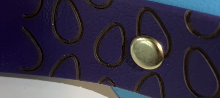
Has anyone encountered an issue where the engraving gets doubled on the X-axis but only in one 4-5 inch section. The rest is crystal clear. I have a creality falcon 10w laser. I’ve taken the whole rig apart and cleaned the rails, wheels, belts. Reassembled ensure it’s square and belts are tensioned. If you can see the picture it’s doubled on the left but clear on the right. This is one continuous engraving
Overscan 5%
Interval 0.7
Speed 2000 mm/m
Power 55%

Hi @Jp1129
Check the preview, unless that shows doubling (which is won’t) this is still some hardware caused distortion, either a mechanical issue, or perhaps electrical issue. Is your setup subject to extra vibration at that point? Is everything tightly back together? Or too tight?
I assume if you choose a completely different design you get a similar issue?
You mention this strip is a continuous engraving. What happens if you set each object if you select “Fill Shapes Individually” and if you’re using “Bi Directional Fill” what happens if you deselect that?
I don’t think making those changes will fix the problem, but it might help you home in on the cause.
1 Like
No evidence of extra vibration, I noticed the x-axis seemed a bit “sticky” around that point that’s why I took the whole rig apart, cleaned it and reassembled ensure everything was tight and square but no luck. Different designs do the exact same thing in the exact same spot. I will try running a test with the settings you mentioned and see what changes if anything. I’ve decided to work around the issue by engraving vertically rather than horizontally and place it in an area that seems unaffected by the issue.
Seems sticky around one specific area on a single axis? Sounds like your gantry system is racked. Also check the drive pulleys set screws that attach to the steppers. Are you absolutely sure they can spin freely without any issues?
I would power the machine off and physically advance the gantry to the area the issues occurring at and compare square/distances to edges in that area compared to the far corners where no issue occurs.
If different designs do the same thing I have a question: If you change the location of the artwork on the bed physically, does the issue occur exactly as before? Or is it slightly different, yet similar.
I had this happen to me on a 3D printer once that ended up having a slightly bent hardened linear rod and it was causing the linear bearings to not be able to ride over the “hump” in the rod. This was essentially a Z axial racking that was occuring due to the gantry not being able to accomodate for the track going up and down with the bent rod.
1 Like
I thought it felt a little sticky but very slight barely able to tell any difference from the rest of the travel. I did check all wheels to make sure they were secure and spin freely, no issues there. I made sure it was square when I reassembled after cleaning. The area that doubles is a little offset from centre towards the left, every other area engraves perfectly crisp and clear. You can see in the pictures on section is crisp and then it gradually gets worse and worse until it’s fully doubled. Then a few inches further it goes back to crisp clean engraving again.
I’m going to flip my engraving 90° so that instead of the x-axis having long sweeps it will be short passes and I’m going to put the piece where the engraving seems to be good as see what that does.


1 Like
Is your acceleration crazy high? It seems to be losing position.
I agree with turning off overscan and bi directional scanning to see how repeatable it is
You would need to hold the rod tight while trying to spin the pulley. Sometimes this slipping is random but will occur near the same spot because how it is failing in relation to a spot in the diameter of the guide rod.I had to disassemble my Xtool d1 pro and grind flats in them. I had almost identical doubling that seemed random and was very difficult to track down because everything was square, and seemed just dandy.
You might also try a bunch of vertical lines spaced at intervals. Run it like 3 passes and see what your fail map looks like then.
I also had a wire loom catching on a corner that caused something similar. It would get hung up, not be able to move at that rate, then catch up, causing a sort of simulated slip…sometimes it is weird / not obvious stuff until you catch it in the wild so to speak.
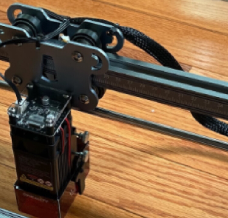
Looking that the Xtool D1 pro vs my unit, I don’t have the same guide rod as the D1. Mine is a solid aluminum rail with tapered inside edges for the wheels to rid in top and bottom. Here’s a picture from google. The rod you see beneath is the drive shaft for the y-axis. Because of this I don’t see how there could be any variation or bend/warp causing the issues as it’s a solid piece of extruded aluminum.
That’s a good idea I’ll try the lines tonight. I thought about a wire loom catching but never observed it happen.
Right, those are guide rails. It can still happen of course, but unlikely. Those extruded rails are usually quite strong, but they are of course subject to failure, mishandling, etc, as is any manufactured item. I agree that this as a point of failure is unlikely.
Looking at the design I immediately see an issue with how far cantilevered past the rail the entire mass of the head is. I imagine at high speed that thing swings back and forth like a pendulum. I see that they likely did it to provide additional vertical clearance to objects, but I feel they mechanically sacrificed…a lot.
If you reduce your speed by half, dies it happen? How about half again?
You will have to adjust power down as well as not to incinerate everything.
If you grab the entire trolley/laser head module/skate, can you twist it along its axis? LIke back and forth like you’re adjusting a volume knob or something. If there is any play at all between your top and bottom guide wheels, I could easily see this generating wobble at specific speeds/geometry combinations.
In that picture the laser module is quite far down, mine sits much higher up than that providing more stability. I would also expect that if that was an issue I would see the effects regardless of what or where I was engraving rather than in one specific area. It’s also worth noting that it being one continuous engraving, the laser module is moving across the x-axis at a constant rate from before the problem area to well after it. There is no acceleration inside the problem area, only the diode firing.
There is zero play between the top and bottom wheels, attempting to move the laser module in any direction yields no movement.
I haven’t tried reducing speed/power yet. More tests for tonight lol.
1 Like
One last question I have is whether or not the bad areas occur while the loom is under tension or when it is lax. Possibly the ramping up of voltage due to a crimped or pinched wire for the power control to laser module. As your beam gets thicker when more power is delivered. Would also track with it being area-specific.
The loom is plugged in on the right side of the gantry and the problem area is closer to the left side. If right is 0% and left is 100% the problem area is somewhere between 60% and 80% travel. All that to say, the loom is fairly straight and not bunched up or tight when the problems happen.
I had the same problem. I also have creality falcon, but doubly as weak - 5 watt. The way I handled it is by adjusting tightness of wheels on top of laser moving assembly. Both of them, until it was not wobbling, but not tighter than that. (it was slightly tighter before that). Check it out and see if you can handle it by use of those two cam adjusters for the rollers.