Yeah, both of mine are on.
Yes, I think you may be on to something with the inverted signals, we had to reverse the polarity and direction of the X/Y axis’s! I’ll see if I can get that LPS wiring diagram!
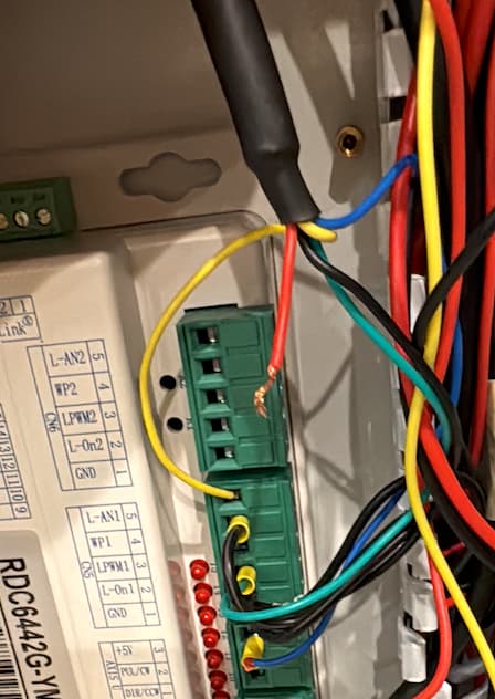
I don’t see a yellow wire in any of your photos?
We need to know what signals are going to the lps, then it’s relatively simple to use a voltmeter and measure them.
It will invert the output… it will also be lasing when it normally is just moving to a different object.
I doubt it will allow it to lase, but it shouldn’t hurt anything.
What are your X and Y axes values after a boot?
If it does or doesn’t boot correctly, it might help us with solving other issues.
![]()
[quote=“jkwilborn, post:22, topic:172463”]
I don’t see a yellow wire in any of your photos?
There is a yellow wire in the bundle of wires coming from the LPS.
What are your X and Y axes values after a boot?
How do I check this? Is it visible on the control panel on the laser?

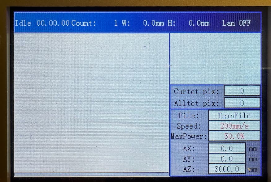
Does it boot up with these values? If it fails the boot routine, the X and Y axes are set to 10,000 or something large.
Which photo is that?
Colors mean nothing to most of us with Chinese machines, they seem to use whatever color they have on hand to wire stuff up.
What we can’t see or help you with is the db9 type connector that goes to your lps. In my photo of the lps, each of the control pins are exposed and labeled.
Did you ask the vendor about this or about getting any information?
![]()
A basic schematic of the unit would be best. Showing the connections from the controller to the lps.
![]()
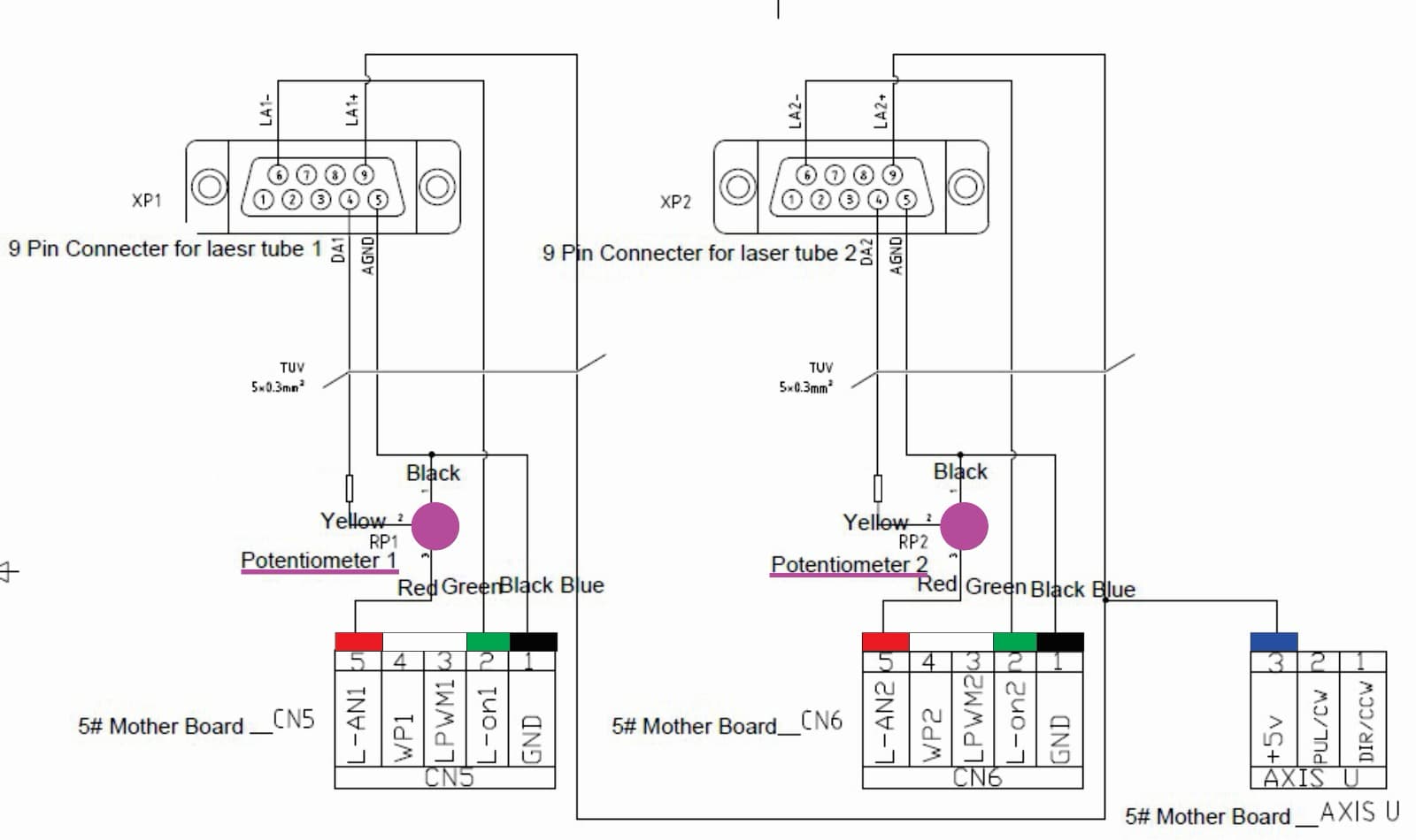
The potentiometer is just a voltage divider for the analog current control signal. Ensure this is turned to it’s maximum. This will limit the range of current produced.
You can check that pin 9 of the db9 is pulled to 5V by the Ruida. This appears to be a positive signal for the lps to lase. It’s using pin 6 as laser enable.
If L-On1 goes low and there is a voltage on L-An1, then it should lase. Ensure the machine isn’t creating any error messages when checking this. The gantry should stop working on an error.
You should be able to check the yellow wire to see if the pot’s working.
Make sense?
![]()
Thanks so much for your help, this is honestly a little above my pay grade haha!
The Pot is at max, it always is.
So turn my voltmeter to AC, put red on the 5V and put the black to 15 and press go?
L-ON1 is set to low by Lightburn.
Check the yellow wire how? This wasn’t initially hooked up to the Rudia, but Camfive said that if I wanted to take the Pot out of the loop to try and hook it up to L-ON1, just to make sure the Pot wasn’t the problem.
Thanks!
All of this stuff is DC.
Not sure what 15 is.. can you clarify?
This is under Ruida control as to when it lases. The code is likely already loaded within the controller.
I don’t think this is right, so lets not do that, set it up as it was.
![]()
@jkwilborn It looks like the L-on1 at pin 6 is being used to sink the U +5V at pin 9? - I wonder why they didn’t just connect pin 6 to GND and then connect L-on1 directly to pin 9 as an active high instead of involving U +5V?
I would read it as LA+ as an active high input and LA- as an active low input. It appears both need to be active. Since the Ruida works with pulling things low, I think it’s the correct option…
If they wanted to use LA+, the I think they’d have wired LA- to ground.
I could change mine to be a positive signal to enable the laser using the H terminal of the lps… However, I don’t think they recommend wiring H to 5V and using L for the enable. I don’t think they mean both need to be active as I know H on mine is open.
![]()
Haha, of course…![]() Im real good with a sewing machine haha!
Im real good with a sewing machine haha!
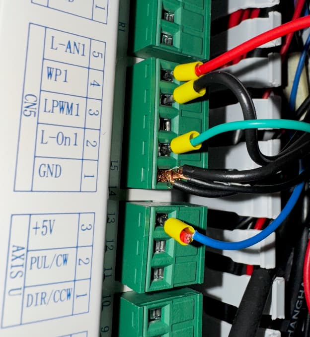
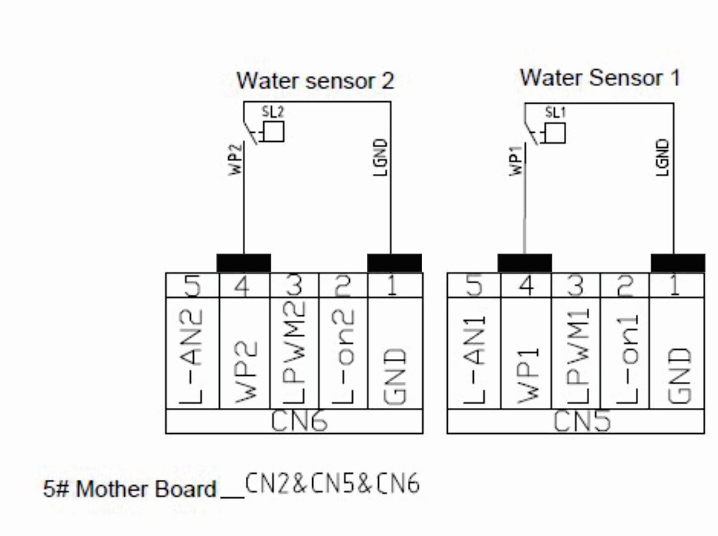
You can check the AXIS U:+5V against CN5:GND, same for L-On1, which should also be 5V when the machine is idle and close to 0V when active.
L-ON reads at 4.6V
#3 reads at 5V
That’s good, and does L-on drop to around 0V when a job starts that would normally fire the laser ?
And when that same test job is running and if it has the power value set to about 50%, do you get a voltage reading of around 2-2.5V between L-AN1 and GND (which should go all the way to 9pin connector(5)).
Check also that the 2-2.5V voltage from L-AN1 is going all the way to 9pin connector(4) - maybe test at the yellow wire after the potentiometer).
L-ON Drops to Zero on run
#3 5V DOES NOT DROP TO ZERO on run.