I just updated my Camfive laser with a new motherboard, and controller so I could use Lightburn on my mac instead of using a PC. I got everything working EXCEPT the actual laser wont fire, Im sure it is a setting in Lightburn that I havent found. I verified that the laser does work with a manual test.
Im using a Rudia Controller
Manual test from the laser power supply (lps) or from the console?
If you’re using your Ruida to handle error messages, then the P input to the lps should be wired to ground, so the Ruida is controlling everything. How are you dealing with a coolant failure?
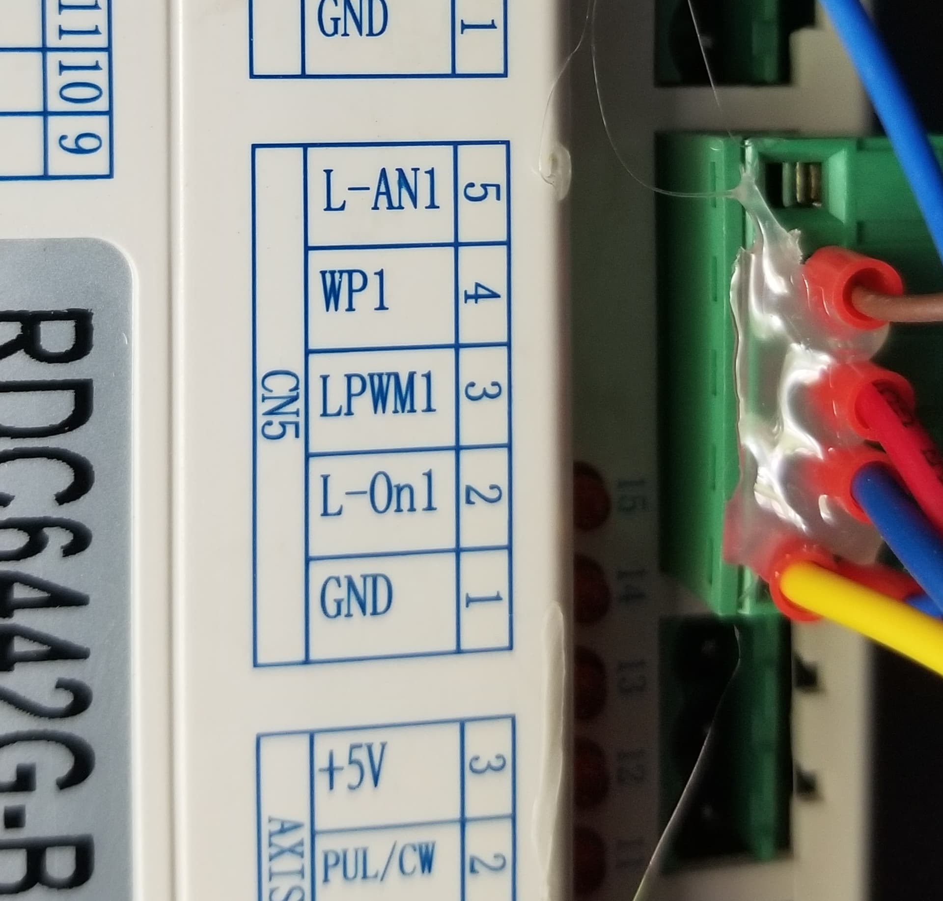
How did you wire the CN5 connection to your lps?
Use either L-AN1 or L-PWM1, but not both. I use L-PWM1 as it seems easier to deal with… doesn’t matter in the end.
| Ruida | LPS | Description |
|---|---|---|
| L-AN1 | IN* | Analog tube current control |
| WP1 | N/A | Input for water protect |
| LPWM1 | IN* | Digital tube current control |
| L-On1 | L | Laser enable |
* Use only one type of input, analog or digital.
Make sense?
![]()
Should I try switching to the LPWM1 output?
NO… It should work either way and you don’t want to monkey with something that should not be the issue. There’s some other obstacle in the way preventing it from lasing.
Can you check your lps to check how P on the LPS is wired up? A photo would be good… ![]()
![]()
Not sure what you mean by the above. P input, coolant failure, and Rudia handling everything… haha. Ive been using the laser on a PC with chinese software prior to this, first time Ive gotten my hands dirty in the guts of this thing!
P on the LPS? Want a pic of the motherboard?
P is power, on the Laser Power Supply, I got it.
My chiller has a signal it sends to the Ruida. If this signal becomes inactive due to a flow or refrigeration issue the Ruida will halt the machine.
On some low cost machines the water protect is wired to P (water protect) on the LPS, you don’t want this with a Ruida. If the low cost machine coolant fails, the controller doesn’t know it and looses it’s position.
A Ruida will halt everything and remember where it was when the failure occurred allowing you to re-start the job where it left off.
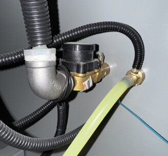
I was wanting a photo that shows the connections to the lps..
Do you have a voltmeter (multimeter)?
![]()
Very strange, I now have a water error message on the Rudia, and the machine wont move. It was moving before with no laser firing. I dont think I changed any settings, I deleted my old file on Lightburn and reloaded it…
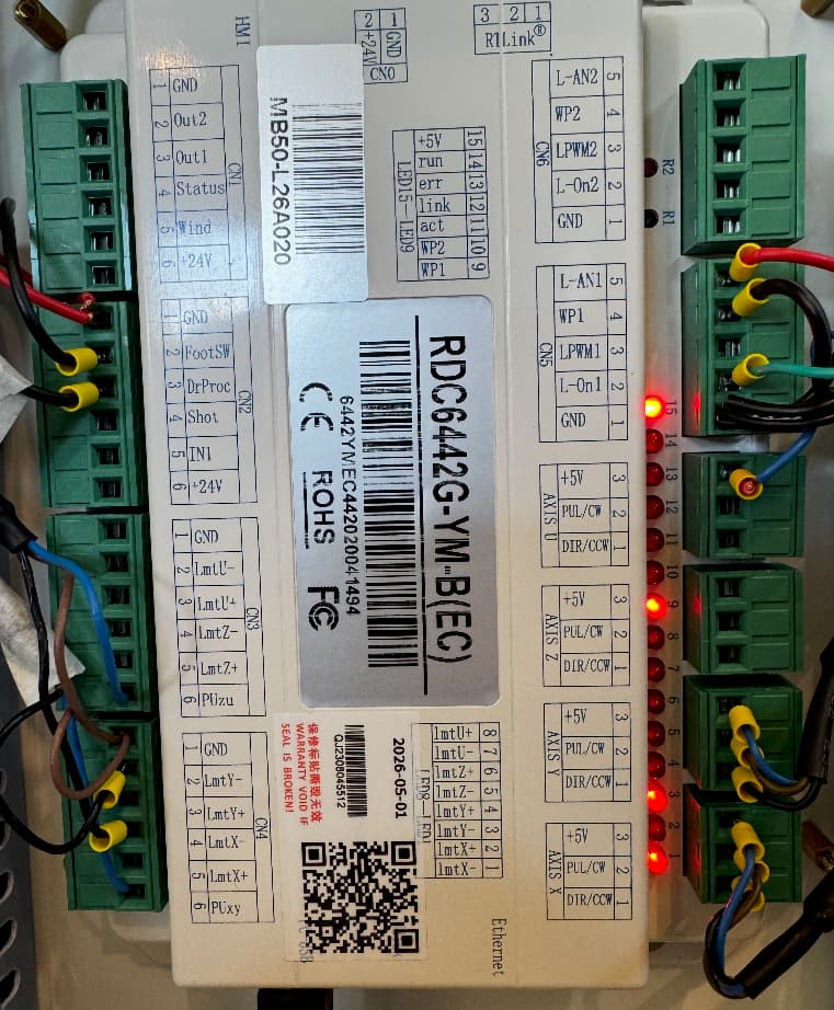
I was hoping for a regular lps… This is mine.
Can’t tell on yours, but I’m pretty confident it’s the same connections, just not visible.
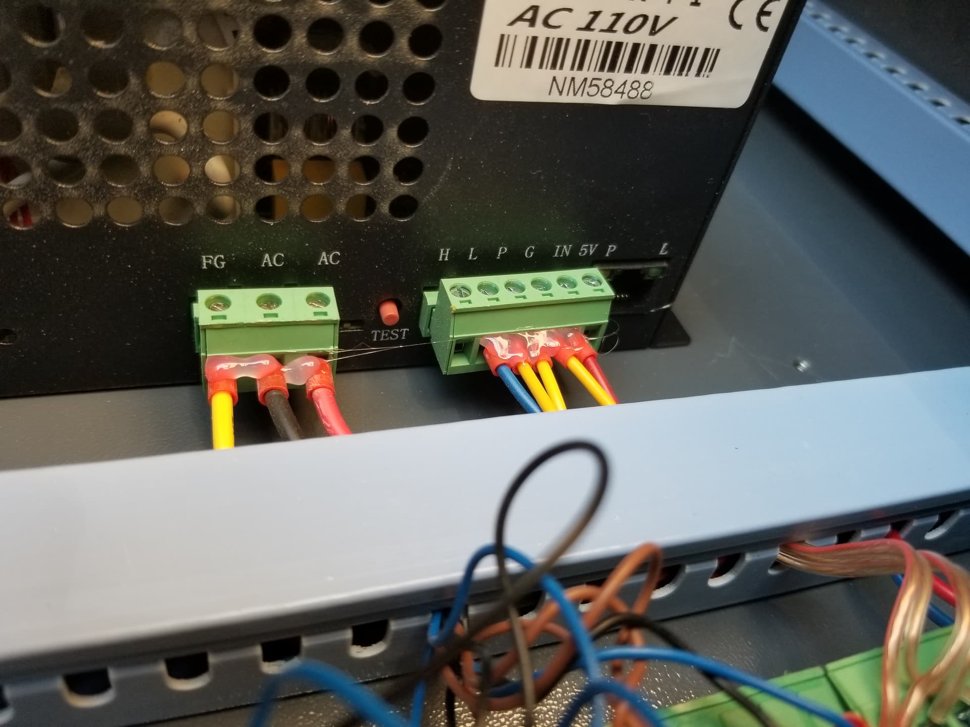
You’re left measuring the Ruida output.
When there is a voltage, like 50% power on the IN terminal and L goes low it should lase.
Can you check these? It’s unlikely the Ruida has failed, much more likely it’s an lps.
![]()
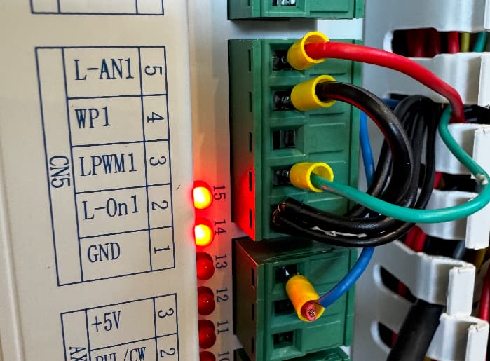
Is the indicator light at 9 still lit? (It should be if water protection is enabled)
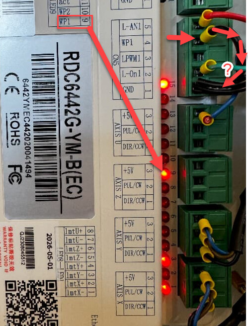
It looks like you might have a have a short wire between WP1 and GND? I could be wrong it’s a little difficult to tell from the photo…?
…if that is not connected, that could be your problem - check the wiring at GND.
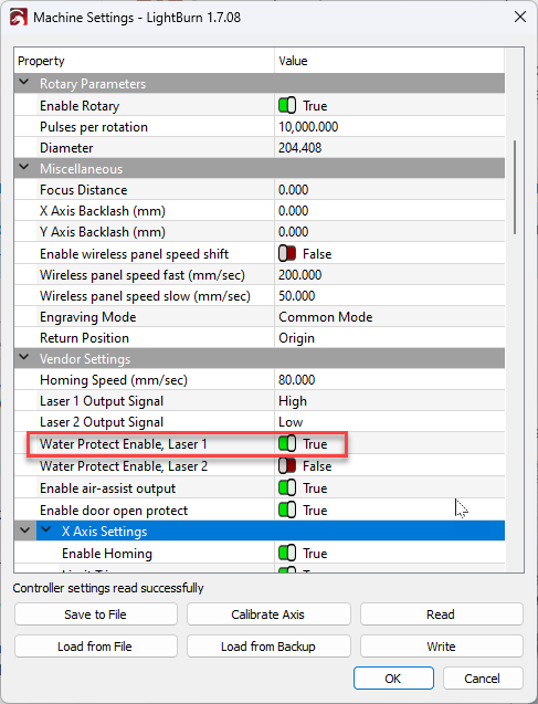
Note: It’s unusual to have this link here at all since it’s equivalent to disabling water protection in the Ruida Vendor (Machine) settings:
There isnt a short jumper wire there, but the water sensor is wired to GND and WP1.
#9 is lit.
I heard from Cam5 that the red wire from the LPS is NOT connected to the Rudia, instead the red wire at L-AN1 goes to the potentiometer on the front or the laser. The red wire from the LPS, is completely disconnected…
Thanks so much for your help…
OK good, if #9 is lit then presumably you are no longer getting water errors at the control panel.
L-AN1 is an output, so if the red wire from there is is going to a potentiometer then it would have to also be going to the LPS (otherwise it would not be doing anything).
If there is a potentiometer in-line with the LPS, then you would have to make sure it was was not dialed right down when testing because you need to allow the voltage signal from L-AN1 to make it through to the LPS.
Is there a model name or description somewhere at the LPS? Do you have a wiring diagram for it?
The other consideration is that the L-On1 sometimes needs to be configured to be an “active high” output, (Machine Settings : Laser 1 output signal : High/Low). If you can get a wiring diagram that would help.
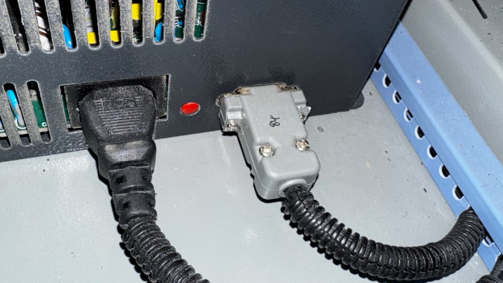
Does this boot? Likely not related to it lasing, but may give us a few more tips on where to look.
What does your machines console say for X, Y coordinates?
After mine boots, both X and Y home leds are off. After mine boots, you can’t get these to illuminate, even by going to a 0, 0 position. Both of yours are on.

Might indicate your machine works with positive values for an active state that @NicholasL was driving. So there could be a number of inverted signals you may have to deal with.. Most are generally handled via the controller configuration.
Completely concur.
![]()
Interesting. I asked my camfive guy if we could bypass the potentiometer and he said to wire the yellow wire into the L-AN1 spot, I tried this and still no luck.
The potentiometer was all of the way up during my previous testing.
The LPS is a 750W High Voltage power supply with the model number GE-045310000029. I might be able to get a wiring diagram from Camfive.
My L-On1 is set to low, would it hurt to try high?