Laser not cutting at the start of a line/curve randomly

I’ve been getting these strange areas where at the start of a cut it is ‘late’ to fire and is generating these missed areas. Now I’ve been around and checked the the flow switch is operating correctly, no lose wires but it seems to occur as seen with the circles at the same point which I would assume isn’t ‘random’ but there is some correlation. Now on the piece below it you see it hasn’t performed this at all and as such was cut correctly.

In the other image where I’m cutting out window sections for a model you see it has done the same but with straight lines and again at the start of the cut.

I’m starting to wonder if this may be software related due to the commonality and repeat areas it is doing such.

Would anyone at all have a hint or maybe solution we can work with to see if I can possible troubleshoot this? It is driving me crazy.

Could you post your .lbrn2 file or the code that this project output?

If you Alt+P do you see the missed sections in the Preview window?

What is the make and model of your machine, and how old is it?

0416 - Sheet 2.lbrn2 (73.9 KB)

The other interesting thing is that I design/create the build file on one pc and then post the designs to my shared folders and open them on the pc that is in the workshop. The speeds are always different and I need to change them but the power % remains the same, so for instance if I open this file now it shows the speed at 40/60. If i open it at the machine the speed is 1800/60.

On preview the details are shown.

So this is a HPC LS3060 which I’ve brought it back upto a new standard recently after taking hold of it. It’s had a new 80W tube installed, new 80W PSU, new cloudray controller, flow switch all the usual age related items. The school it was from I’ve spoke to them before and it was a low hour machine already but it was old electronically.

Image of the machine now back to a modern standard.

I’ve done a little more research and tried these, so I’ve lowered my start speed to 3mm/s from 10 and it still occurs. I’ve also added a laser on delay of 5ms and it still occurs.

This is the full sheet results of the above file for reference and you see it is on the circles mostly but some edges.

@Colin Do you have any idea as to what could be causing it?

Export the settings from the machine you like and import them into the other:

Most likely, there’s a mismatch between [inch |millimeter] and [second | minute].

With the two machines equalized, make sure you have the LightBurn workspace set to the same units in both machines while you’re working at them:

@ednisley Hi Ed, when you refer to the two machines is in terms of the computers as I’m currently only running this one laser cutter.

So would the above if I share the same settings between the two computers fix this intermitant line that’s not being cut at the start of a new cut sequence?

Whenever this situation comes up:

Then at least some of the problem involves two different LightBurn configurations on the two different PCs, so the first step (at least for me) is to equalize the configurations.

While doing so doesn’t always solve the problem, it does eliminate a huge time sink while we identify and eliminate the differences One. By. One. during the next week.

In addition, (at least some) Ruida controllers can display speeds & distances in either metric or 'Murrican units, so verify the laser setting matches the LightBurn settings for both the machine and the design:

Then we can maybe figure out what else is kaflooie. :grin:

Had to look this one up. Imperial units! Not everything American is goofy! :rofl:

Nowadays it’s a good first approximation. :frowning:

(Further, I sayeth not.)

Ed, you are preaching to the choir. It is easy to see how Adolph got his start. <\rant>

Hi @ednisley

I’ve just done the export and import bundle as above following the lightburn pages. I’m still getting the same issue of speeds changing on sending the file. So a 450mm/s is being changed to 7.5mm/s which is a clean factor of 60 so not even like it’s a metric to imperial conversion factor.

Just to clarify incase it is how I am doing such, I Import my design into lightburn on one pc and do all the config there regarding speed/power and any tolerances for offsets and save the file then locally in a shared directory linked by the cloud. I then open that file on my laptop connected to my laser cutter and that then is where I see the change, I have also tested it the other way and the factor still exists but multiples the speeds so they’re often upwards of 3000mm/s.

I agree to solve this first before trying to look at this intermittant cut issue.

Rob

Check to be sure that’s not the difference between 450 mm/min and 7.5 mm/s.

1 Like

@ednisley Good freaking spot sir! It’s staring right at me in the face too. So obvious too being divisible by 60, damn I feel like an idiot :rofl: I wouldn’t mind I only just paid for my yearly update fee and just pushed the new updates to both PC’s, corrected the other pc to mm/s. Thankyou!

So, an issue that wasn’t an issue and was a problem behind the keyboard. Hopefully we can now try to look into this issue of the cuts not occuring at the start of some lines/curves. Would you have any idea where to start on this?

I hate it when that happens around here. :grin:

At this point, I assume:

  • The two machines now agree on units
  • What you see on one is what you get on the other

If that’s not the case, we must figure out why before proceeding.

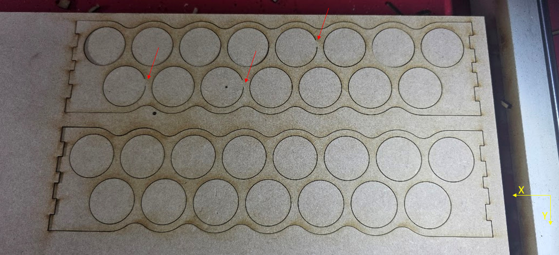
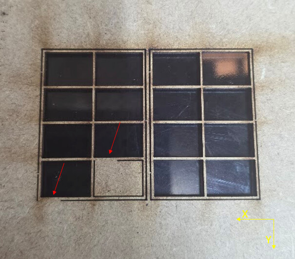
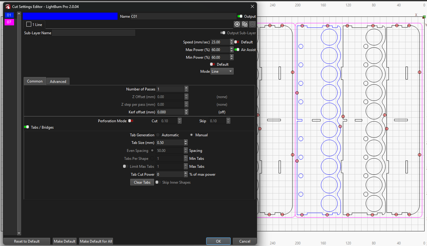
The file you provided seems match your second picture.

On my system, the circles start (and end) at their top.

The file has Automatic tabs set, with one 0.2 mm tab per shape. The tabs are on the bottom of the circles, opposite the start/stop point, and there is one tab on each large outer perimeter near the top of the shape.

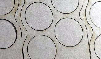
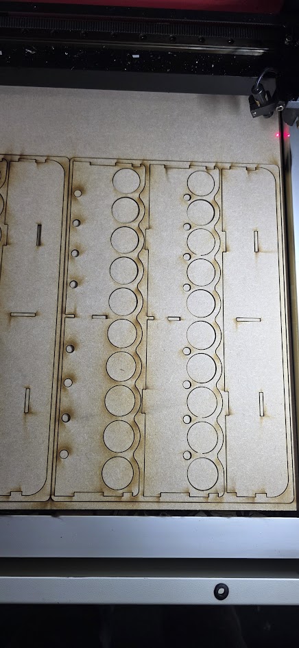
Your picture does not show any trace of the tabs and the orientation seems to be reversed:

  • The perimeters gaps are near the bottom
  • The circle gaps are near the top

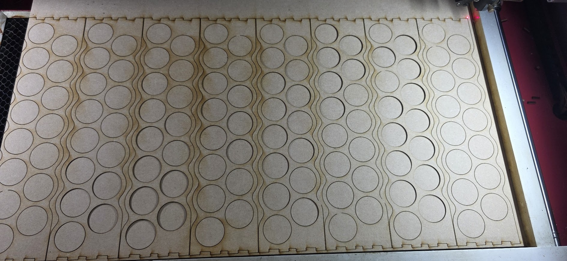
Even without visible tabs (some circles appear to fall freely), the laser tube seems to be shutting down (correctly) at each tab and sometimes failing to restart (obviously incorrectly) after the tab.

Verify that by running the same design on cardboard (because cheap) until it fails, then scrubbing through the Preview to verify which direction the laser head is moving at each failure. If those failures match the position of the tabs, then that’s useful evidence.

Assuming that’s the case, I suspect the power supply is developing a problem: it sometimes does not fire the laser tube correctly after a brief interruption.

Because it does fire correctly when the tube has been off for longer durations, like after the head moves from one shape to another, you can (probably) work around this for a while by turning off the tabs.

If you really need tabs, making them longer than 0.2 mm may give the power supply time to recover.

Replacing the power supply is relatively inexpensive and straightforward, so if you really need short tabs, I’d try that first.

I suspect the power supply is failing, rather than the tube, because the supply controls the voltage and current to the tube. However, it’s all basically guesswork.

@ednisley Thankyou, so we’re good on the issue of parameters being different now.

For some reason this particular file has them turned on now on my other designs they are turned off as I have manual ones placed to ensure the kits stay together but the issue is persisting on those too but not in the places where I have put tabs as the tabs seem to correctly be produced.

For instance another kit type here with the manual ones only three of the circles on the right have experienced this issue -

I’ll have to get back to you on the cardboard as I don’t have any on hand.

Regarding the PSU this is a brand new cloudray 80-100W unit so I’d like to think it would be ok but I’ve learned over the years new can still be faulty. Is there a method currently to test this theory you know of? I can reach out to cloudray if not to see how their perspective may be.

My guesstimate of where the tabs were in relation to the start of the circles could be off by 180°, so it’s entirely possible the misfires occur at the circle starting points in addition to tabs on the perimeters. That would invalidate my guess about the tube not firing after tabs, but that’s what more evidence will do for incorrect notions.

What does the Preview show at the places where the misfires occur?

Amazon is not a thing near you? :grin:

Basically, if you can live with wrecking good material, have at it. We try to discourage folks from ruining priceless wood slabs, but sometimes … :grin:

One useful test, however, would be varying the layer power to determine if misfires happen more or less frequently depending on the power.

Definitely start a warranty conversation with them, including matched sets of designs + results.

AFAICT, there is no LightBurn setting along the lines of “screw up occasionally” in the way you’re seeing. That will not prevent Cloudray from claiming it’s not their [mumble] problem, but if they can’t point to anything other than the power supply, then I’d say there’s the problem.

I think I could capture evidence with an oscilloscope, but I’m certain I can’t talk you through the process if you’re not already familiar with such things. :electric_plug:

@ednisley So, I did some more messing around last evening and some more today with parameter sets and changes. I do bring some progress at least, I reached out to cloudray and not yet received any response but I do have some news.

I manually added a start pause to my cuts for this layer + power % to 50% and over rode the fq to ensure it definately is at 20khz. Since doing this I’ve rarely experienced the issue, now it hasn’t fully cured it but I may only get say 1 piece still having the miss firing issue at the start of a cut out of a few kits so It has drastically improved the results.

Would these findings present you with any additional ideas or confirm thoughts as to the issue at all?

That definitely shows the tube is not firing immediately when commanded. Waiting 50 ms gives it enough time to (almost always) fire, which means something is going wrong at 0 ms.

You could guesstimate the delay times using an array of squares. The length of the gap on the side of a failed square corresponds to the firing delay, using the RepRap calculator to figure how long it takes for the laser head to travel that distance along a straight line from a standing start.

Removing the tabs shows the problem happens after the laser has been off during the move to the shape and, after the tube lights up, it remains lit until the end of the path. You can verify that by using the Preview to see which way it moves along the shapes.

The Override PWM Frequency should have no effect, because the high voltage power supply filters the PWM input to extract the power level. That filter has a cutoff around 200 Hz, so pretty nearly any PWM frequency will work fine. Disable the override and I expect nothing will change.

It’s either the power supply or the tube and I’m still thinking “power supply”.